A PLC (Programmable Logic Controller) has some similarity to a personal computer (PC). It has a microprocessor, memory, input and output interfaces. However, unlike a PC, it does not have a keyboard, mouse, monitor or hard disk. And before for you ask, no – it can’t surf the net, check your social media status or play your favorite music and games.
A PLC is a specially designed digital controller that is microprocessor based and can be easily programmed to perform complex control tasks. They have been purpose-built for industrial applications in order to provide control and automation to machinery and processes with high accuracy and reliability. Programmable Logic Controller is more often than not abbreviated to PLC.
The most important difference between a Programmable Logic Controller and a Personal Computer is that the operating system of a PLC is extremely stable and reliable compared to a PC. PLCs have been specifically designed to be used in industrial automation applications so they also have a robust housings, higher interference immunity, built-in industrial communication protocols and are able to efficiently interface with large amounts of input and output devices.
A Brief History of the Programmable Logic Controller
The father of the PLC is noted as being Richard E Morley. Commonly known as Dick Morley, he was an American engineer who was an expert in the field of computer design, artificial intelligence and automation receiving numerous industry awards throughout his career. He was born in Clinton, Massachusetts on December 1, 1932 and died on October 17, 2017, in New Hampshire.
Dick Morley is credited with the invention of the Programmable Logic Controller in 1968. He lead the team that spearheaded the development of the first PLC while he was at at Bedford and Associates. The invention of the PLC was fuelled for the need to automate the General Motors production facility.
The first Programmable Logic Controller was called a Modicon PLC. The name was a shortened version of modular digital controller. The introduction of the Modicon PLC revolutionized industry and how industrial processes and machines where automated.
Modicon was the company that created the Modicon PLC in 1968. But since then Modicon have been owned by Gould, AEG and are presently owned by Schneider. PLCs have certainly come along way since their inception +50 years ago.
What are Programmable Logic Controllers Used For?
Programmable Logic Controllers are used to automate tasks that where traditionally controlled by hardwired relay logic control systems. PLCs are used to automate tasks like pushing, lifting, sorting, cutting, flipping, weighing, transporting, washing, drying, stacking, welding, sanding etc. The tasks that a PLC can be used to automate are virtually endless.
The difference between a PLC and a relay is that a PLC is a microprocessor based device whereas a relay is an electromechanical switching device. In order to provide intelligent control of processes and machinery a PLC needs to be programmed whereas relays need to be wired in combination with other relays.
Because PLC architecture is based on a computer microprocessor, it is not restrained to only perform hardwired relay logic type operations. Programmable Logic Controllers can also perform other operations such as comparison, mathematics, timing, counting, sequencing, analogue signal processing, data manipulation and more.
The industrial applications of a PLC are numerous. They are used to automate applications such as assembly lines, fan and pumping systems, batching plants, robotics, material handling conveyors, stockpiling and reclaiming machines, packaging systems, grinding and milling plants, building management systems etc. The list of application is virtually unlimited.
Programmable Logic Controllers have penetrated into almost every industry. Some of the industries that PLCs are used in include, but are not limited to, are manufacturing, mining, oil and gas, food and beverage, logistics and baggage handling, timber processing, irrigation, waste water processing, metal fabrication and welding, textiles and chemical processing.
What are the Advantages and Disadvantages of a PLC?
To realize the advantages and disadvantages of programmable logic controllers we need to compare them with other types of control systems.
The 4 main types of controllers used in industrial control systems are relay logic, industrial PCs, microcontrollers and PLCs. Each type of controller has it’s advantages and disadvantages. The type of controller that is best suited will depend on the type and size of the automation application.
A PLCs is best suited to automate a large amount of automation tasks, such as a manufacturing plant. Relays are best suited to automate a hand full of simple automation task, such as hopper level control. A Microcontrollers is best suited to automate an application with a fixed set of parameters and has potential for mass production, like a washing machine. While an Industrial PC would be best suited when high degrees of math computation is required, such as a flight simulator.
The difference between a PLC and a microcontroller lies in the architecture of the units. Both have a microprocessor with inputs and outputs, but a PLC is designed to be expandable, accept and process large amounts of I/O and be able to communicate with other devices. Whereas a microcontroller is usually purpose built for one particular automation task, at lower cost and usually for mass production purposes.
What are the Advantages of a PLC?
The main advantages of a PLC are listed below:
- Compact and robust.
- Extremely reliable operating system.
- Fast processor execution time.
- Virtually maintenance free.
- Easily expandable due to its modular design.
- Lower power consumption compared to relay systems.
- Built in communication for remote I/O, instrumentation, other PLCs and SCADA.
- Can handle a large number of digital inputs and outputs.
- Able to process analogue input signals and PID loops.
- Multiple programming languages available.
- Large programming instruction set.
- Easy to use programming interface via PC.
- Control logic modifications easily done via software, no hard wire modifications required.
- Installation costs greatly reduced compared to relay systems.
- Excellent documentation facilities.
- Increased ability for fault finding and diagnostics.
What are the Disadvantages of a PLC?
- For simple applications where relay logic might suffice, using a PLC might blow out costs due to the need to hire a programmer.
- Math functions in a PLC are quite advanced, but when it comes to doing large amounts of complex math computations then an industrial PC might be better suited.
- Certain robotic and positioning applications may require extremely high speed execution which may not be able to be achieved form a PLC.
- Can be expensive for automating an application with fixed parameters for mass production as compared to a microcontroller.
How Does a PLC Work?
The basic elements of a PLC that make it work are the Central Processing Unit (CPU), data memory, program memory, input modules and output modules. The PLC CPU continuously monitors the input signals, formulates decisions based on the application program and then controls the output signals to automate a process or a machine. The Programmable Logic Controller stores the application program in the program memory and stores the status of the inputs and outputs in the data memory.
A microprocessor based CPU (Central Processing Unit) is what controls processes within the PLC. The block diagram below simplifies the process flow within the PLC. The inputs are read and their status stored in the data memory, the data is transferred to the application program and processed, the data memory is updated and finally the outputs executed.
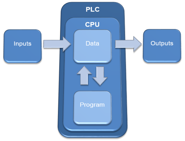
Inputs are field devices such as button, switches and instrumentation which are used to decide when and how the machine will operate. Inputs are wired directly into to the PLC or via input modules.
Outputs are field devices such as relays, motor contactors, solenoid valves, lamps and sirens which cause the machine to operate and provide feedback to the machine operator. Outputs are wired directly out of the PLC or via output modules.
Data Memory is where inputs and outputs are declared and allocated to memory locations. The data memory stores the status of the inputs and outputs and is continually updated by the application program.
Program Memory is where the application program (such as ladder diagram) is stored and processed. The program memory needs to be loaded with a program so that it can do stuff. If there’s no application program loaded in the program memory, the PLC is just an expensive paper weight.
Basic Operation of a Programmable Logic Controller
Even though a PLC has a CPU just like a PC, the internal operation is not quite the same. PLCs are designed to be extremely reliable and therefore have a fixed and dedicated internal process. This process is called the PLC scan cycle.
The PLC scan cycle is a sequential and repetitive process that has 3 basic tasks. Evaluate inputs, process the application program and execute outputs. The tasks in the PLC scan cycle are strictly performed in a certain order and in an endless cyclical manner.
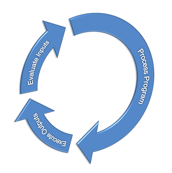
Some Programmable Logic Controller from different manufacturers may have slight variations to the scan cycle, but the 3 tasks mentioned above are common to all.
The PLC scan is part of the second task (process program) in the scan cycle and refers to the way in which the CPU processes the application program. During the PLC scan the rungs of the application program are processed from left to right and top to bottom. The CPU continually updates the status of each the inputs, outputs and internal variables in the data memory but only executes the outputs at the end of the PLC scan.
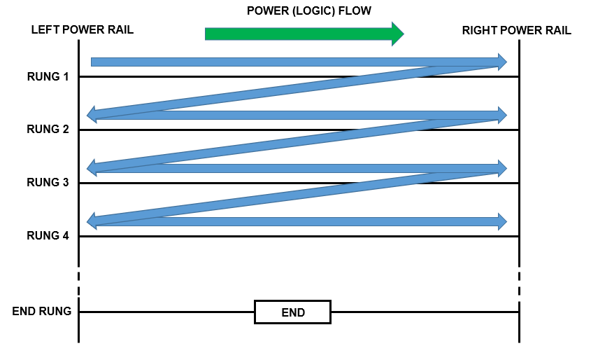
This is super important to remember because it can affect the way the program is evaluated. As a consequence the PLC Scan sequence may force you to modify the way your application program is written in order to achieve the correct process control outcome.
The scan time is the total time that it takes for the PLC to complete one full scan cycle. The scan time is universally expressed in milliseconds (ms). The PLC scan time is an essential metric to measure and be aware of because it can have adverse effects on the PLCs ability to control the application, especially if the speed of your application is faster than your PLC scan time.
In summary, the basic working principles of a PLC is that it monitor the status of the machine and process, then makes decisions bases on the logical functions created by the ladder logic program stored in the PLC’s memory. The Programmable Logic Controller then initiates output signals to control the behavior of the machine or process.
PLC Automation
When it comes to industrial automation the PLC is literally considered to be the “brains of the operation”. It’s a programmable device that makes all the decisions on how a machine is controlled depending on the data gathered from field instrumentation and operator feedback.
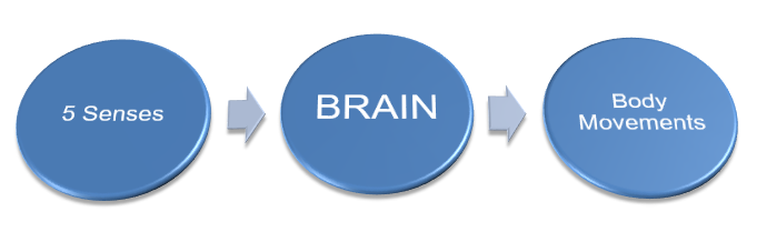
To better understand PLC automation we can compare to how the human brain works. If we look at the human brain we realize it relies on our five senses of sight, hearing, smell, taste and touch to understand what our environment is doing. Also, the human brain controls movement in our body to create actions such as walking, running, kicking a ball etc.
So let’s say we sense that our body is getting hot. Then we can roll our sleeves up a little too cool down. We can actually roll our sleeves up and down to regulate our body temperature to what feels comfortable. If we’ve rolled up our sleeves all the way and we are still too hot after a certain amount of time and we can’t tolerate it any more then we can take our sweater off.
How would a Programmable Logic Controller Automate an Industrial Application?
Just like the human brain relies on information provided by our senses, a Programmable Logic Controller requires instrumentation to measure it’s surroundings. These are known as PLC inputs.
And just like the human brain uses data gathers from the body’s senses to decide on what actions are required to be taken, a PLC gathers information from instrumentation and uses the application program to decide what actions are required to be taken.
The information gathered by instrumentation is stored in the data memory and the application program is stored in the program memory.
Lastly, just like the brain controls movement in our body, a PLC controls movements in a machine using electric, pneumatic and hydraulic devices. These are known as PLC outputs.
Let’s Connect a Programmable Logic Controller with Input and Output devices for a Basic Temperature Control Application.
If we connect a temperature sensor as a PLC input we can measure how hot it is. Then if we connect an electric fan as a PLC output we can regulate the temperature.

A PLC is just a boat anchor if it does not have a program stored in its memory. For a PLC to automate an application we need to define our control objectives in order to be able to program some control logic expressions.
A basic functional description of a basic temperature control application could be….
- If the temperature measured increases above a certain threshold, the Programmable Logic Controller can switch an electric fan on to cool down the system.
- Then if the temperature measured increases or decreases the Programmable Logic Controller can adjust the speed of the fan to regulate the temperature to maintain a certain level.
- Once the temperature reduces below a certain threshold, for a certain period of time, then the electric fan can be switched off.
Remember, the level of PLC automation is only as good as the information gathered by instrumentation and the quality of the application program contained in it’s memory. So a good program with solid logic expressions will ensure trouble free operation.
A PLC can control industrial automation applications. The amount of applications that a PLC can control are endless, but here are just a few examples….
- Controlling the level of a process water tank by monitoring the tank level and varying the speed of an inlet pump.
- Controlling the temperature of a drying oven by monitoring it’s internal temperature and varying the burner control valve position.
- Controlling the starting and stopping sequence of a series of material handling conveyors.
The PLC Control System
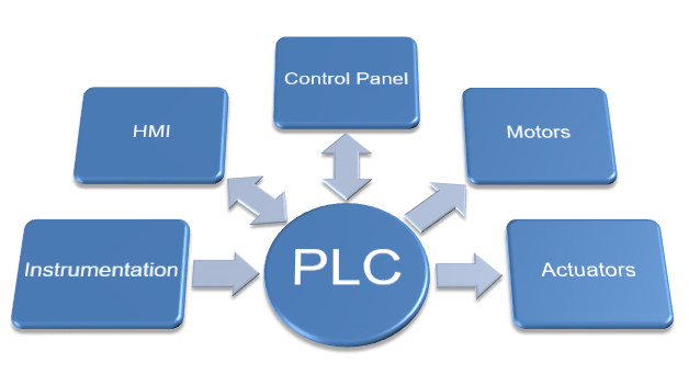
A PLC system is the combination of various hardware and software components. Each component plays a specific and important role in the overall PLC control system. The essential elements that make up a PLC control system are the PLC itself, peripheral input and output devices, Human Machine Interfaces (HMI) and a programming device.
PLC Input devices include instrumentation like switches, sensors and push buttons. PLC Output devices include equipment such as electric motors and actuators. They are either hardwired to the PLC or connected via a fieldbus (communication link) such as Ethernet IP, Profibus, Modbus etc).
Human Machine Interfaces (HMI) form the bridge between the operator and the PLC by allowing operator control and providing visual and audible feedback. They include devices such as touch screens, SCADA systems (Supervisory Control & Data Acquisition) and hardwired control panels that have switches, push buttons and indicator lamps.
A PLC Programming device is needed to be able to configure and program the PLC control system. In the past dedicated programming terminals were used, but today a PC is the tool of choice.
The PLC System works by accepts the input device signals, process the data according to the program stored in the PLCs memory and then activating the appropriate outputs to control the machine or process.
A basic block diagram of PLC control systems is shown below:
Because a Programmable Logic Controller is specialized to execute it’s scan cycle it performs with high speed and with extremely high reliability. This is essential for maintaining high reliability for PLC machine control and process automation.
Imagine the Programmable Logic Controller crashing, just like your home PC operating system, midway through a machine operation. It can be dangerous to personnel, production and equipment causing injury, damage, downtime and unnecessary expense.
Programmable Logic Controllers have also been designed, unlike the home PC, to operate under harsh industrial environments where electrical noise and Electro Magnetic Interference (EMI) exist.
They generally, but not always, require a separate power supply and have input and output terminal strips for connection of electrical devices. For some PLC machine control applications extendable and remote mounted input and output modules are usually available.
These days PLC machine control systems have communication options such as Ethernet/IP (Allen Bradley), Profinet (Siemens) and Modbus TCP/IP (Modicon), to name a few. PLC machine control system communication options such as these allow for networking with other PLC’s, remote input/output modules, instrumentation, motors, actuators and Human Machine Interfaces (HMI) such as touchscreens and SCADA systems.
In the next section we will examine the current PLC Manufacturers in today’s automation industry, their ranking, revenues and the latest PLC products on offer. To go to the next section click here.
If you’d like to learn the basics of ladder logic programming then click here.