A PLC (Programmable Logic Controller) is made up of both hardware and software components. The PLC hardware refers to the physical components that make up a PLC system. Whereas the PLC software refers to the PLC’s operating system and application program that are stored in the PLC’s memory.
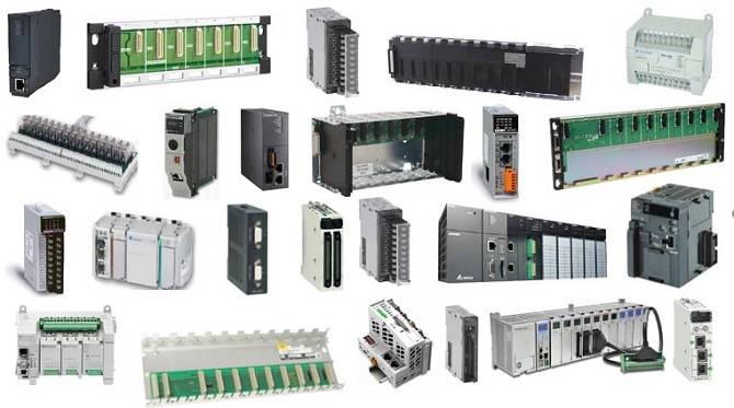
PLC hardware is a term that describes the physical components that make up the overall PLC system. Each piece of PLC hardware is designed to perform a specific task. Without all of its hardware components a PLC system cannot operate effectively.
Think of the main components that make up a car. The engine, gearbox, wheels, electrics, steering, body etc. Without all of its components a car cannot function properly. And most of the components that are used, say in a Ford, cannot be used in a Honda. In that sense, PLC Hardware is a similar concept.
The majority of PLC manufacturers have developed hardware and software components to establish a proprietary PLC system. That means PLC hardware components vary for different manufacturers and in the majority of cases are not interchangeable with hardware components from other PLC brands.
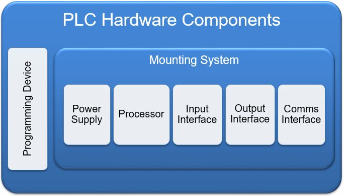
The 6 basic hardware components that make up a PLC are:
- Processor (CPU)
- Mounting System
- Power Supply
- Input & Output Interface
- Communication Interface
- Programming Device
These main PLC hardware components are found in all PLC systems regardless of manufacturer, type and size. They are the essential hardware elements that make up every PLC system.
Let’s take a closer look at the major plc components and their functions…
1. PLC Processor (CPU)
At the heart of every PLC system is a processor. It is arguably the most crucial PLC hardware component. Sometimes the PLC processor is also referred as the PLC controller or PLC CPU (Central Processing Unit). Whatever you choose to call this piece of PLC hardware, the PLC processor is the workhorse of the PLC system responsible for all the logic computation and number crunching.
The PLC processor can be embedded into the PLC unit or come as a separate PLC module. Generally fixed PLC types have their processor embedded in the PLC itself. While modular and distributed PLC types have their PLC processors as a separate module.
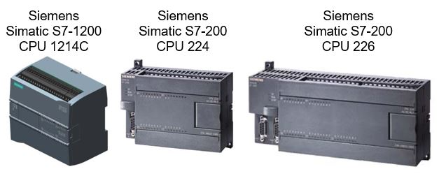
Some examples of PLCs with embedded processors are the Siemens Simatic S7-200 CPU 224, S7-200 CPU 226 and more recently the Siemens Simatic S7-1200, CPU 1214C (6ES7 214). They are a fixed style PLC with embedded processor, but have the ability to expand with input and output modules. See below….
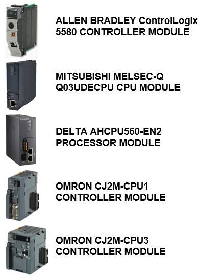
Some examples of PLC processor modules are the Allen Bradley ControlLogix 5580 controller, the Mitsubishi Melsec-Q Processor CPU (Q03UDECPU), the Delta AHCPU560-EN2 processor and the Omron CJ2M-CPU1 and CJ2M-CPU3 controllers.
The PLC processor contains 3 fundamental components:
- PLC CPU (Central Processing Unit)
- PLC Memory
- PLC Programming port
PLC CPU (Central Processing Unit)
The PLC CPU is a microprocessor that is similar to a computer CPU. However, the PLC CPU is not set up to multitask like a computer CPU, but rather to perform dedicated tasks such as program scan and execution.
In a PLC the CPU is responsible for control of all PLC activity. This includes program scanning (such as ladder logic), program executing, handling data storage, directing data flow and controlling communication among the various interfaces.
The most common processor used in a PLC is a single microprocessor. However, the higher powered PLCs have multiple microprocessors to divide up the various tasks in order to improve overall operating speed. A PLC with dual microprocessors could have a control processor to carry out data manipulation and complex computation as well as a second logic processor to execute the logic, timing, counting and other functions of the application program.
PLC Memory
The PLC memory is made up of program memory, data memory and firmware. The PLC uses the memory to store the program for processing by the CPU and to store data for input and output processing and execution.
The size of the PLC memory will vary depending on the processing power of the CPU. You will find that higher powered PLC models will be equipped with faster CPUs and will have more onboard memory.
So if you have a large PLC program then you will require a PLC controller with a large integrated memory capacity to accommodate. Having said that, some PLC controllers have expandable memory which can get you out of trouble if you run out of memory unexpectadly.
PLC Programming Port
The programming port on the PLC processor is used to connect to a programming device such as a PC or laptop. The communication protocol used for the PLC programming port varies between PLC manufacturers. Some examples of the communication protocol used for the PLC programming port includes RS232, RS485 and Ethernet.
2. PLC Hardware Mounting Systems
The hardware mounting system of a PLC provides the means to physically connect the various hardware components of the PLC system. PLC hardware mounting systems can vary from one PLC manufacturer to another and can also vary depending on the type of PLC used.
The 3 main PLC mounting systems used in industrial automation projects are:
- Rack mounted PLC
- Rail mounted PLC
- Panel mounted PLC
Let’s look at the different mounting systems in a little more detail….
Rack Mounted PLC
A rack mounted PLC uses a mechanical mounting system in order to physically connect the PLC processor and other PLC hardware components together. The most common rack mounted PLCs use an arrangement whereby the hardware components are slotted into the rack. This allow the hardware components to be secured in placed and at the same time connected together, with plugs at the base of the rack, via the PLC bus.
Rack Mounted PLCs are commonly used in modular and distributed type PLC systems. They are well suited to service higher end and plant wide applications where multiple PLC racks and large numbers of inputs and outputs are required. They have a fixed number of hardware module slots and generally have an orderd hardware module layout. Such as power supply module, PLC processor module, communication modules then input and output modules.
An example of a rack mounted PLC is the Siemens Simatic S7-400. The PLC mounting rack, rack slots, PLC bus and PLC modules are clearly labelled. This particular PLC mounting rack has 9 slots, with some PLC hardware modules taking up multiple slots. See below….
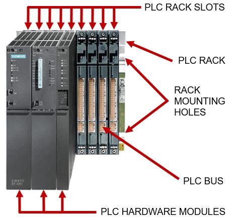
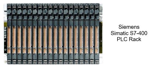
Some PLC manufacturer use different terminology to describe their rack mounted PLCs. Terms such as chassis, backplane, base, base rack and base module are all examples of different terminology to describe rack mounted PLCs. Siemens uses the term PLC rack for their S7-400 PLC mounting system.
An example of a Siemens PLC rack is shown below…
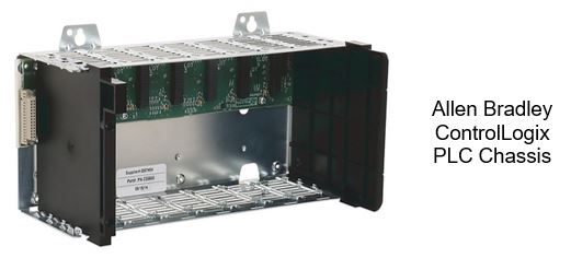
Allen Bradley uses the term PLC chassis for their ControlLogix PLC mounting system. An example of an Allen Bradley ControlLogix chassis is shown below….
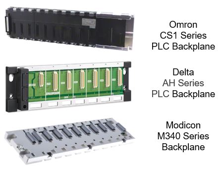
The term PLC backplane is used by the the Omron CS1, Schneider Modicon M340 and Delta AH series PLCs to describe their PLC mounting system. Examples of the Omron CS1 series PLC backplane, Delta AH Series PLC back plane and Modicon M340 backplane are shown below…
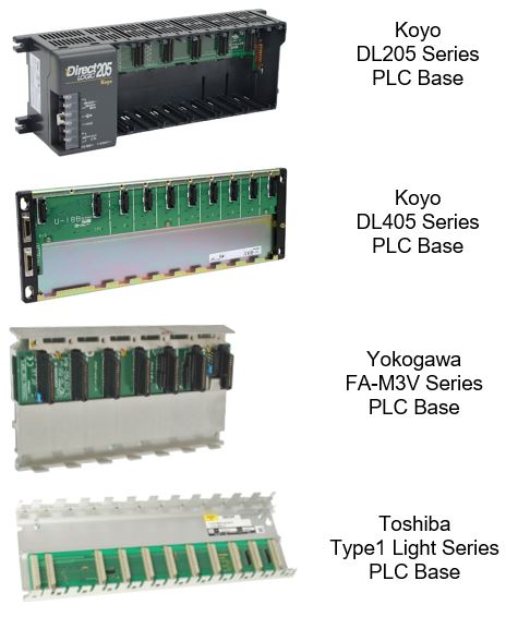
Koyo, Toshiba and Yokogawa use the term PLC base to describe their PLC mounting systems. Examples of the Koyo DL205 series PLC base, Koyo DL405 series PLC base, Yokogawa FA-M3V PLC base and the Toshiba Type 1 Light Series PLC base are shown below….
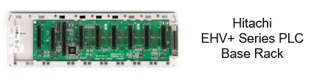
Hitachi uses the term PLC base rack for their EHV+ Series PLC mounting system. An example of a HitachiEHV+ Series PLC base rack is shown below….
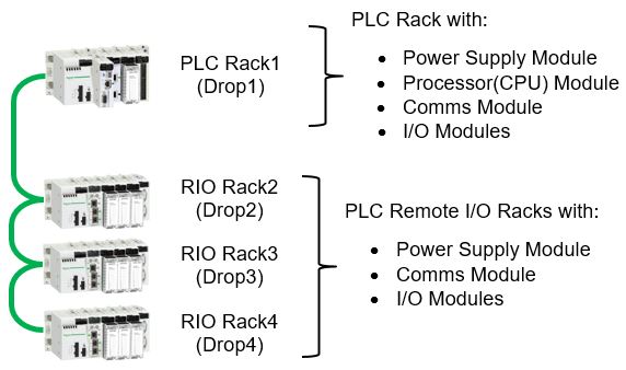
The term PLC Rack is commonly used to describe a group of PLC hardware components that have been installed into any given PLC mounting system. A PLC rack can also be referred to as a PLC Drop. If a PLC rack has only input and output modules installed (no Processor CPU) then the PLC rack is called an I/O Rack or a Remote I/O (RIO) Rack (usually located away from the main PLC rack).
Remember the term PLC drop and RIO drop can also be used when referring to PLC racks and RIO racks. A simple example of a PLC rack connected to multiple RIO racks is shown in the diagram below….
Rail Mounted PLC
The PLC mounting rail is commonly known as DIN rail. It is made out of metal and provides a means of mechanically securing the PLC hardware components. The PLC mounting rail is generally screwed into an enclosure pan and then the PLC hardware components are clipped or screwed in, side by side.
DIN rail is an industrial rail mounting system that was developed in Germany in the 1920s. It has become extremely popular and is now extensively used for mechanically mounting of a variety of electrical components such as terminal blocks, circuit breakers, power supplies, PLCs, relays, timers etc.
The 2 most common PLC mounting DIN rail types are:
- 35mm DIN rail
- Siemens Simatic DIN rail
PLC 35mm DIN Rail Mounting
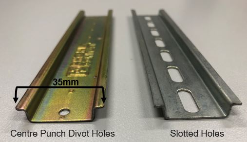
The 35mm DIN rail has kind of a D shaped profile and comes in various pre-cut lengths, but can also be easily cut to size. It measures 35mm in width from the LHS edge to the RHS end. Most 35mm DIN rail comes with either center punch divot holes or slotted holes in the base to allow ease of installation with mounting screws into an electrical panel.
The PLC hardware components that can be mounted on DIN rail have been designed with a mounting arrangement on the back of the component. There is a hook like arrangement on the upper side and a clip type arrangement with release/engage slot on the lower side. The pictures below shows the basic PLC 35mm DIN rail mounting system.…
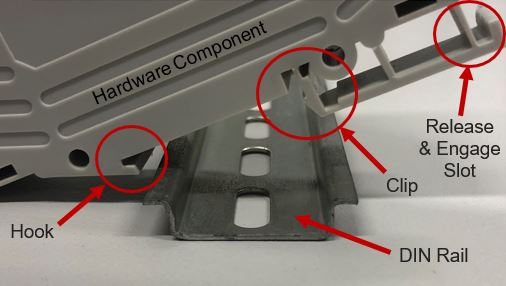
DIN rail works by hooking the back of the electrical component into the upper part of the rail and then pushing it towards the DIN rail until the lower part clips in. The DIN rail release mechanism works by using a flat head screw driver to pull down on the spring loaded tab at the bottom rear of the electrical component while using an upward lifting motion to unhook it from the top part of the DIN rail.
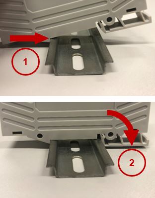
To install a PLC hardware component onto DIN rail follow the steps below:
- Grab the PLC hardware component and hook it onto one side of the DIN rail.
- Lever the PLC hardware component down toward the DIN rail until it clicks in. If the component does not have a spring loaded clip, then the clip will need to be manually released (pulled out) and engaged (pushed in) with a flat head screw driver.
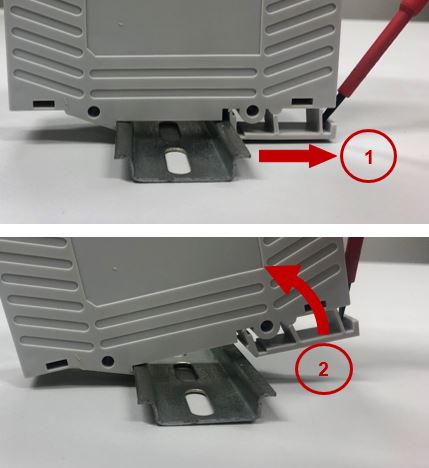
To remove a PLC hardware component from DIN rail follow the steps below:
- Grab a small/medium sized flat head screw driver and place it in the clip slot. Pull the clip out by applying a force on the screw driver in the opposite direction to the DIN rail. Usually you can lever the screw driver against the PLC hardware component case to make it easier.
- Hold tension on the clip using the screw driver as you lift the PLC hardware component up and out past the edge of the DIN rail. If the component does not have a spring loaded clip, then the clip is simply released (pulled out) with a flat head screw driver, there’s no need to hold tension while levering up and out.
Siemens Simatic PLC DIN Rail Mounting
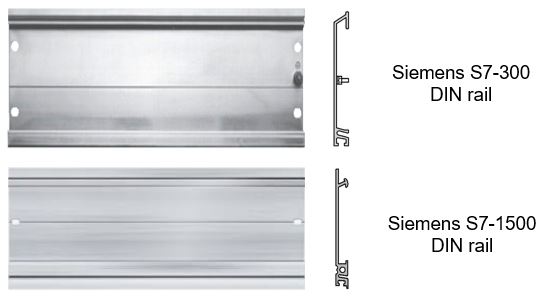
The Siemens PLC DIN rail is only for use with the Siemens S7-300 PLC and the Siemens S7-1500 PLC. The Siemens S7-300 DIN rail and the Siemens S7-1500 DIN rail have a different profile so they cannot be interchanged. They both can be ordered in various predefined lengths 160mm, 245mm, 482mm, 530mm, 830mm and 2000mm.
Below is a picture of both the Siemens S7-300 DIN rail and the Siemens S7-1500 DIN rail…
The Siemens PLC DIN rail works in a similar manner except it is screwed in at the bottom instead of clipped in.
Rail Mounted PLC Hardware Component Connection
The 3 most common methods that rail mounted PLCs use to connect their hardware components together on the mounting rail via the PLC bus is with:
- Ribbon cable connectors
- Plug and socket connectors
- PLC bus couplers
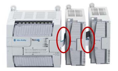
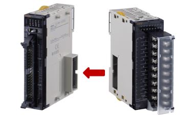
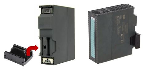
The type of PLC bus connection for rail mounted PLC will depend on the PLC Manufacturer. For Example Allen Bradley MicroLogix 1200 PLC uses a ribbon cable connectors, the Omron CJ1 Series PLC uses plug and socket connectors and the Siemens Simatic S7-300 PLC uses PLC bus couplers.
Terminology Used to describe Rail Mounted PLCs
The terminology to describe a PLC with a mounting rail can vary depending on the manufacturer. Some examples that PLC manufacturers use to describe rail mounted PLCs include:
- DIN rail PLC
- Rack less PLC
- Plugin PLC
- Modular PLC
- Expandable PLC
- Stackable PLC
- Snap In PLC
- Side by Side PLC
Panel Mounted PLCs
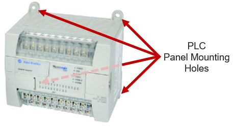
A panel mounted PLC uses a mounting system that directly mounts the PLC and its hardware components without the additional need for a rack or rail. A panel mounted PLC will have mounting holes molded into the PLC housing and PLC modules, usually around the edges of the PLC housing.
Fixed PLC types are usually designed to be panel mounted. But a lot of fixed PLCs combine panel mounting holes and a DIN rail mounting facility as well. Also, Modular PLCs that are DIN rail mounted sometimes have combined DIN rail mounting and panel mounting holes. The Allen Bradley ControLogix 1200 is a panel mounted PLC, but also has the facility to be DIN rail mounted. See the picture below….
To install a panel mounted PLC onto the pan of an electrical enclosure you need to:
- Mark where the mounting holes need to be on the enclosure pan using a template provided in the installation manual or the PLC itself.
- Drill and tap the enclosure pan mounting holes.
- Place the bolts (with washers) through the mounting holes provided on the PLC housing then screw and tighten the bolts into the enclosure pan.
Some people prefer installing panel mounted PLCs using self-tapping screws because it’s quicker. BE CAREFUL here because some industrial sites have electrical installation standards that do not allow mounting of electrical equipment with self-tapping screws.
3. PLC Power Supply
The main purpose of a PLC power supply is to convert the available power supply voltage into a voltage that is usable by the PLC processor (CPU) and other PLC modules. The most common PLC power supply input voltages are 120VAC, 240VAC, AC voltage range (like 85-265VAC) and 24VDC. While the most common PLC power supply outputs are 24DC and 5VDC.
There are 3 main types of PLC power supplies:
- Integrated PLC power supply
- PLC power supply module
- Remote PLC power supply
An Integrated PLC power supply is embedded in the PLC processor. Fixed type PLCs and some modular type PLCs have their PLC power supply embedded in the PLC processor. A PLC power supply module is separate to the PLC processor but is mounted on the same PLC rack as the PLC processor. While a remote PLC power supply is mounted away from the PLC rack and hard wire connected to the PLC processor.
PLC Power Supply Mounting
Most PLC manufacturers mount their PLC power supply modules at the LHS end of the rack. But some can be mounted on the RHS end or in the middle of the rack. Some PLC power supply mounting examples are below:
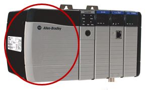
The Allen Bradley ControlLogix PLC Power Supply is mounted at the left end of the PLC rack….
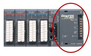
The Koyo DirectLOGIC 305 PLC Power Supply is mounted at the right end of the PLC rack….
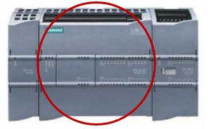
The Siemens Simatic S7-1200 Power Supply is integrated into the CPU Module….
PLC Power Supply Connection
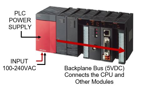
The output of the PLC power supply is usually seamlessly connected to the PLC processor (CPU) and other PLC modules by plugging directly into the PLC backplane bus. For example the Mitsubishi Melsec with Q61P PLC power supply has 100-240VAC input voltage and 5VAC output voltage via the PLC backplane bus to the CPU and other modules. See the diagram below….
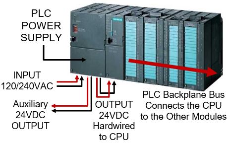
Some PLC power supplies require hard wire connection from the PLC power supply to the PLC processor and other PLC modules. Sometimes auxiliary 24VDC output terminals are provided on the PLC power supply for use with field instrumentation. If the PLC power supply does not have auxiliary 24VDC output terminals then a separate 24VDC power supply is required for use with field instrumentation.
The Siemens S7 300 PLC power supply has 120/240VAC selectable input voltage and requires a 24VDC hardwire connection to the PLC Processor (CPU). But the connection from the PLC CPU to other PLC modules is done via the PLC backplane bus. Also Siemens S7-300 PLC power supply has auxiliary 24VDC terminals that can be used for field instrumentation. See the diagram below….
PLC Power Supply Size
The PLC power supply size will depend upon the overall size of the PLC system. It’s important to select the correct size of PLC power supply to maintain a stable PLC system. The more input and output modules that are mounted on the PLC rack, the larger the PLC power supply size will need to be.
It is common to specify the PLC power supply size in power (W) or apparent power (VA). If the PLC power supply input is AC then the size will be in power (W) or apparent power (VA). If the PLC power supply input is DC then the size will be in power (W). The PLC power supply output is always DC, so the size will also be expressed in power (W).
The PLC power supply input size is useful for determining the power feed requirement and protection for the PLC power supply module. But the PLC power supply rating data is what is needed to accurately select the correct PLC power supply.
PLC Power Supply Rating
The PLC power supply rating is generally specified in Voltage (V) and Current (A). In actual fact, it’s the output PLC power supply rating that is required when choosing a PLC power supply because the total current load of the combined modules on the PLC rack must not be greater than the PLC power supply rated output current.
Another important factor that affects the PLC power supply rating is the ambient temperature rating. If the ambient temperature is kept within the specified limits then the PLC power supply will perform as specified. Otherwise it will need to be de-rated to avoid overheating. To de-rate the PLC power supply simply means that the load on the PLC power supply is reduced in order to decrease the output current draw.
The Allen Bradley ControlLogix 1756-PA50 data sheet has an example of PLC power supply de-rating for increased ambient temperatures. It states that the output current rating for 24VDC at 50 DegC is 2.5A and at 60 DegC it reduces to 2.0A. If there is a situation where the ambient temperature exceeds the maximum ambient temperature rating specified, then extra cooling to the PLC cabinet will be required.
The various PLC manufacturers all have different PLC power supply sizes and they pick and choose what ratings and specifications they include on their PLC power supply labels. If there is some information not contained on the label it may be located in the PLC manufacturers’ data sheets. Having said that, all PLC manufacturers will specify the PLC power supply output voltage and current ratings.
Some examples of PLC power supplies and their output ratings are shown below:
- Mitsubishi Melsec Q61P PLC power supply, 5VDC 6A
- Schneider Quantum PLC Power Supply 140CPS11400, 5.1VDC 8A
- Siemens S7 300 PLC PLC Power Supply PS-307, 24VDC 5A
- Allen Bradley ControlLogix PLC Power Supply 1756-PA72, with multiple backplane voltages-(1.2VDC 1.5A) (3.3VDC 4A) (24VDC 2.8A) (5.1VDC 10A)
Check out some examples of different PLC power supply labels….
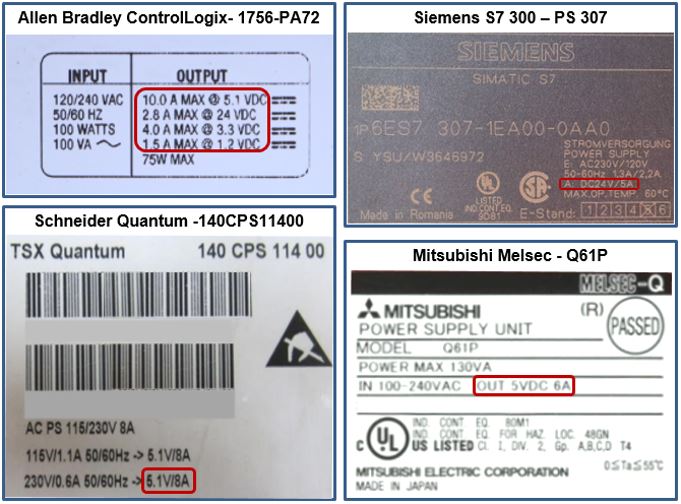
Below is a PLC Power Supply Rating Table comparing the label specifications shown above.…
| Manufacturer | Allen Bradley | Mitsubishi | Schneider | Siemens |
| Brand | ControlLogix | Melsec | Modicon Quantum | Simatic |
| PLC Power Supply | 1756-PA72 | Q61P | 140CPS11400 | S7-300 |
| Power Input | 100W/100VA~ | 130VA | Not Shown | Not Shown |
| Frequency Input | 50/60Hz | Not Shown | 50/60Hz | 50-60Hz |
| Voltage Input | 85-265VAC | 100-240VAC | 115/230VAC | 120/230VAC |
| Current Input | Not Shown | Not Shown | 1.1A(115VAC) 0.6A(230VAC) | 2.3A(120VAC) 1.2A(230VAC) |
| Power Output | 75W Max | Not Shown | Not Shown | 138W Max |
| Voltage Output (DC) | 1.2V, 3.3V, 24V, 5.1V | 5V | 5.1V | 24V |
| Current Output (DC) | 1.5A(1.2VDC) 4A(3.3VDC) 2.8 (24VDC) 10V(5.1VDC) | 6A | 8A | 5A |
| Operating Temperature | Not Shown | 0-55 DegC | Not Shown | Max 60 DegC |
4. PLC Input and Output Hardware Interface
In an industrial PLC system the PLC input and output modules are a common interface between the field devices and the PLC processor (CPU). The PLC inputs and outputs are generally connected to the field devices via a terminal strip. Communication modules with fieldbus protocols like Ethernet IP, Profinet etc. can also be used as a PLC input and output interface.
In a PC (Personal Computer) the input and output interface is the connection between the peripheral devices and the PC. The keyboard and mouse are examples of input devices and the USB port is an example of the input interface. The monitor is an example of an output device and the monitor port is an example of the output interface.
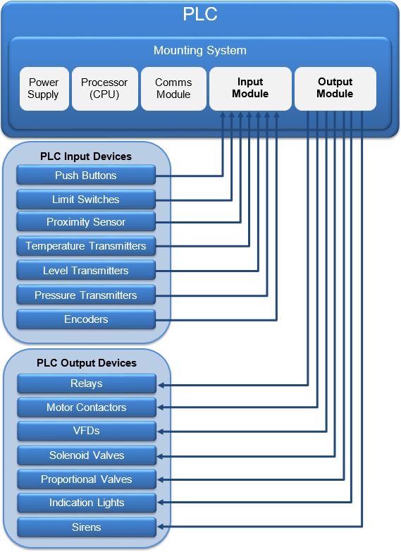
In a PLC, the inputs are connected to PLC input devices like pushbuttons, limit switches, proximity sensors, temperature transmitters, pressure transmitters, level transmitters, encoders etc. And the PLC outputs are connected to PLC output devices such as relays, motor contactors, VFDs (Variable Frequency Drives), solenoid valves, proportional vales, indication lights, sirens etc.
See the PLC Inputs and Outputs block diagram below…
Types of PLC Input and Outputs
The 2 main types of PLC input and output signals are analog and digital (discrete). Analog and digital inputs both measure external field conditions and report it back to the PLC processor (CPU). And analog and digital outputs both send command signals from the PLC processor (CPU) in order to activate field devices. So what’s the difference?
The main difference between PLC analogue I/O and digital I/O are:
- Signal Format
- Signal Wiring
- Signal Processing
The signal format is the main difference between PLC analogue and digital signals. Analog input and output signals are a variable value which change between a specific value-range. Whereas digital input and output signals follows the binary principle and are either ON or OFF.
PLC analog inputs (AI) and analog outputs (AO) are signals that are variable in nature. They measure or output a variable signal that lies between a specific value-range. The most common signal types are 0-10V and 4-20mA. Some examples of analogue inputs are temperature sensors, pressure sensors, weight meters and flow meters. While examples of analogue outputs are motor speed control, proportional solenoid valves.
Digital inputs (DI) and digital outputs (DO) are wired normally open (NO) or normally closed (NC). They are either ON or OFF. Some examples of digital inputs are limit switches, push buttons, proximity sensors, temperature switches. While examples of digital outputs are motor start relays and solenoid valves.
PLC analog and digital signal wiring is also different because of the inherent difference in signal format. In most cases analog I/O also requires a screened cable to suppress signal interference from external electromagnetic sources.
PLC analog and digital signal processing in the PLC CPU is also different. Analog I/O requires at least 1 word (16 bits) of data per I/O point while digital I/O only requires 1 bit of data per I/O point.
PLC Input and Output Modules
PLC inputs and outputs can be embedded in the PLC processor (CPU) or come as an input and/or output module. When PLC inputs and outputs are embedded in the PLC processor they cannot be changed. But when PLC input and output modules are used they can be combined to form a custom arrangement of PLC inputs and outputs.
PLC inputs and outputs that are embedded in the PLC processor (CPU) are usually associated with fixed type PLCs. Whereas, PLC input and output modules are usually associated with modular and distributed type PLCs. Some PLCs have a combination of embedded inputs and outputs in the PLC processor and input and output modules to allow expansion.
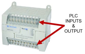
An example of a PLC with embedded inputs and outputs that are onboard the PLC processor is the Allen Bradley MicroLogix 1200. The inputs and outputs onboard the processor are fixed and cannot be changed. However, the Allen Bradley MicroLogix 1200 does also have optional PLC input and output modules available for expansion.
The Delta AS series PLC is an example of a modular PLC with PLC input and output modules that can be arranged to provide a custom arrangement of inputs and outputs.
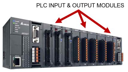
The most common PLC input and output modules are Digital Inputs (DI), Analog Inputs (AI), Digital Outputs (DO), Analog Outputs (AI), Thermocouple Inputs, Resistive Temperature Detector (RTD) Inputs, Load Cell Inputs and Encoder, High Speed Counter and Positioning Inputs and Outputs.
What is the function of the PLC Input and Output Modules?
PLC input and output modules are usually called PLC I/O modules (or PLC I/O cards), for short. They can be a dedicated input module, a dedicated output module or a module with a combination of both inputs and outputs. PLC input and output modules are mounted alongside the PLC processor (CPU) and can be selected and arranged according to application requirements, making them inherently flexible.
The main function of PLC input modules is to condition the input signals received from the field devices into a format that the PLC processor accepts. The main function of PLC output modules is to condition the output signals sent from the PLC processor into a format that the field devices accept.
Along with conditioning the input and output signals to and from the PLC processor, the PLC I/O modules also provide electrical isolation between the I/O modules internal electronic components and its terminal connections. Electrical isolation is necessary to protect the PLC I/O modules internal electronic components and is usually done optically with optocouplers, sometimes called optoisolators.
PLC Input and Output Hardware Connection
There are various PLC input and output connection methods. Some connection methods are more tedious than others. In general connection of field devices to PLC inputs and outputs is a labor intensive exercise, especially when there are large volumes of PLC I/O.
The most common PLC input and output hardware connection methods are:
- Hardwire connection with terminals
- Fieldbus network connection
The diagram below shows PLC input and output connections using both the hardwire connection and fieldbus network connection methods….
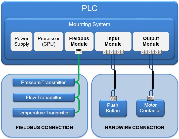
Hardwire connection of PLC inputs and outputs involves running multi-core cables from the PLC input and output modules to the field devices and connecting the wires at both ends, usually with screw terminals.
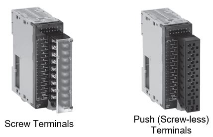
Some PLC manufacturers have plug in terminal options for their PLC input and output hardwire connection. Plug in terminal options other than screw terminals are designed to speed up PLC I/O wiring installation time. The main plug in terminal options for PLC I/O connection are:
- Screw terminals
- Push (Clamp) screw-less terminals
- Wiring looms
- Wiring Modules
An example of a PLC that has a removable terminal strip with screw terminal block and screw-less clamp terminal block options is the Omron CJ1 Series PLC, see below….
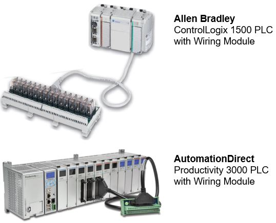
Prefabricated PLC I/O wiring looms or wiring modules are designed to make hardwire connection even easier and less time consuming for installers. For example the Allen Bradley MicroLogix 1500 and the AutomationDirect Productivity 3000 PLCs both have wiring modules with prefabricated cables that plug into the PLC I/O modules instead of having to wire each PLC I/O point individually, see below….
Fieldbus network connection of PLC input and output devices involves a network connection such as Ethernet I/P, Profinet, etc. Connection of PLC input and output devices using the fieldbus network requires a fieldbus module, unless the fieldbus network port is embedded in the processor module.
The latest Ethernet based fieldbus networks such as Profinet, Ethernet IP, Ethercat, Modbus TCP/IP, etc. can be daisy chained if the field devices have an Ethernet switch built in. Otherwise complex networks can established using external Ethernet switches. Older 2 wire fieldbus networks such as Profibus, DeviceNet, Modbus RTU, etc. can be daisy chained with complex networks established using repeater and splitter devices.
5. PLC Communication Hardware Interface
PLCs can communicate to multiple devices by using a communication interface. The communication interface has communication ports which allows cable connection to devices such as other PLCs, remote I/O drops, fieldbus devices, touch screens, programming PCs and servers. Multiple communication interfaces may be required for larger and more complex applications.
The PLC communication interface can exist as either embedded communication ports on the PLC processor or as communication modules. If there is a need for multiple communication interfaces then it’s quite common to see both embedded communication ports on the PLC processor and extra communication modules slotted into the rack.
PLC communication ports commonly use either a Serial based communication protocols or Ethernet based communication protocols. Serial communication ports on a PLC usually use D-sub connectors or terminal connectors, while Ethernet communication ports usually use RJ45 connectors.
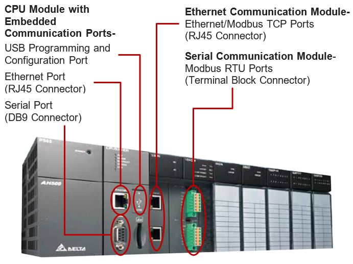
Some popular Ethernet based protocols used for PLC communication include Ethernet IP, Profinet, Ethercat, Modbus TCP/IP and BACnet IP. With Serial communication ports, some of the common protocols are DeviceNet, Profibus DP, Modbus RTU, CANopen, BACnet MS/TP, MPI, DirectNet, RS-485, RS-422 and RS-232.
PLC communication ports that have serial protocols are now considered “old school” by some. However, they are readily available, generally cheaper and are still useful in certain applications. However they are generally slower and cannot handle the same data bandwidth as modern day industrial Ethernet based protocols.
6. PLC Programming Device
The last, but by no means the least, is the PLC programming device. Programmable Logic Controllers need to be programmed somehow. There are 2 devices that can do it.
The two most common PLC programming devices are handheld programming devices and personal computers (PC). Both are used to develop the PLC program (like ladder logic) and then transfer it into the PLC memory. The PLC programming devices connect to the PLC using a cable and transfer the PLC program using either an Ethernet or Serial based communication protocol.
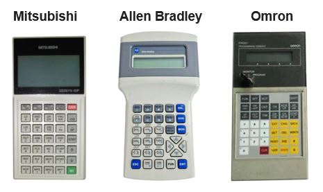
Handheld programming devices are propose built to develop PLC program. But they have limited programming memory, have a very basic display, simple keyboard input functions and are slow and tedious to use. They are generally limited to programming small applications with low numbers of I/O.
Examples of PLC hand held programmers (HHP) from Mitsubishi, Allen Bradley and Omron are shown below….
PC programming devices enables use of large amounts of programming memory (Hard Drive or Solid State Drive) and has a monitor, keyboard and mouse allowing easy and fast programming. The PLC program is developed using the PLC manufacturers programming software application that is installed onto the PC operating system (like Windows). It allows quick and easy programming of complex applications with large amounts of I/O. In fact, nowadays, you’ll find most PLCs are programmed with a PC.
If you are interested in learning the basics of a PLC (Programmable Logic Controller) click here.