
PLC timers are frequently used in ladder logic programming. There are many different types of PLC timers, each with their own unique operation and application. Here we will explore some real world PLC timer examples, draw out the ladder diagrams and explain their operation.
A common real world example of using an ON delay timer would be introducing a delayed start to a conveyor and sounding a warning siren before it starts rotating. Another example, using an OFF delay timer, would be to delay a conveyor from stopping allowing it to empty so it is ready for a re-start.
Some ladder logic timer examples that are commonly use while PLC programming are….
- ON Delay Timer Example: Delay Start with Warning Siren
- ON Delay & OFF Delay Timer Example: Flasher Timer
- OFF Delay Timer Example: Delay Stop
Let’s have a look at each one of these examples in a little more detail…
1) ON Delay Timer : Delay Start with Warning Siren
Nowadays most conveyors in factories and mine sites sound a warning siren before they start rotating as a safety precaution for operators and maintenance staff. The siren warns anyone near the conveyor of an imminent start and the delay allows them to get clear of the conveyor as to avoid injury.
A common real world example of using an ON delay timer is to delay the start of a conveyor while sounding a warning siren. The conveyor start command activates the ON delay timer and siren at the same time. After the time delay expires, the siren turns OFF and the conveyor starts running.
With conveyor start warning siren examples we use the ON delay PLC timer to both delay the start of the conveyor and also turn the siren OFF after the delay time expires. We can build on the previous motor control ladder diagram latching example and introduce an ON delay timer to trigger the delayed start and sound the warning siren.
Because we are trying to accomplish two actions (warning siren and motor run) we’ll need to add an intermediate internal variable to replace the M1 RUN output. It’s not essential, it’s just good practice. Maintaining a neat and simple programming structure is important. Otherwise you’ll find your code will become messy, cluttered and hard to follow.
Let’s call the internal variable START COMMAND with address M1.0 (remember, PLC manufacturers use different memory address allocation so M1.0 is an arbitrary address).
Below is the list of inputs required, no change to the previous ladder logic example…..
| NAME | ADDRESS | TYPE | COMMENT | PLC WIRING |
| M1 START | I:1.0 | BOOL | Motor No.1 Start Push Button | Normally Open |
| M1 STOP | I:1.1 | BOOL | Motor No.1 Stop Push Button | Normally Closed |
| M1 TOL | I:1.2 | BOOL | Motor No.1 Thermal Overload | Normally Closed |
Next let’s add the extra siren output, M1 SIREN…..
| NAME | ADDRESS | TYPE | COMMENT | PLC WIRING |
| M1 RUN | O:1.0 | BOOL | Motor No.1 Run | Normally Open |
| M1 SIREN | O:1.1 | BOOL | Motor No.1 Siren | Normally Open |
We also need to add an extra internal variable, M1 START COMMAND….
| NAME | ADDRESS | TYPE | COMMENT |
| M1 START COMMAND | M:1.0 | BOOL | Motor No.1 Start Command |
Finally let’s add the ON delay timer, T1….
| NAME | ADDRESS | TYPE | COMMENT |
| T1 | T1 | TIMER | Motor No.1 Start Delay Timer |
Now we can add the required control logic by using the M1 START COMMAND to trigger each action on a different rung.
Remember…..Both M1 STOP and M1 TOL are wired normally closed (NC) to the PLC inputs to make them “fail safe” and thus need to be configured as normally open (NO) symbols in the ladder diagram.
Check out the motor control ladder diagram with delay start warning siren below…
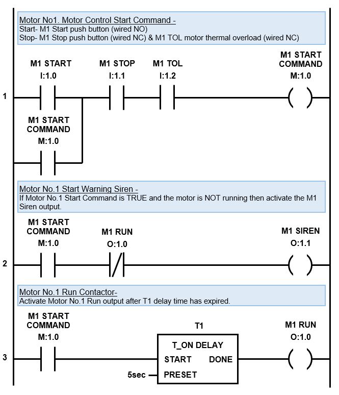
The first rung works the same as the standard motor control latching logic previous example. The only difference is we replace the M1 RUN output with an internal variable called M1 START COMMAND. This enables us to use the M1 START COMMAND latch to trigger multiple actions.
After the first rung is scanned it moves to the second rung. If the M1 START COMMAND is TRUE on the first rung and the M1 RUN output is FALSE (motor is not running) then M1 SIREN output is activated.
Please Note – The M1 RUN output symbol is triggered from the third rung.
The scan then jumps to the third rung and if the M1 START COMMAND symbol is TRUE then T1 TON delay timer is activated. After the M1 START COMMAND is TRUE for 5 seconds (preset time) the T1 TON delay timer will activate the M1 RUN output and then Motor No.1 will start running.
That’s not the end of the story, because the siren is still activated. So, when the PLC scan cycles back to the top and moves through the rungs, if the stop inputs have NOT been triggered, the M1 START COMMAND latch will still be active.
So, when the scan gets to the second rung the M1 START COMMAND symbol is still TRUE and the M1 RUN output is also TRUE (the motor is now running). However, the M1 RUN symbol is normally closed (NC), so when it is TRUE, no logic flows and the M1 SIREN output goes FALSE and switches off.
In the first rung, if either the M1 STOP or M1 TOL (thermal overload) inputs are activated, then logic flow is broken in the latching logic and the M1 START COMMAND goes FALSE. This also breaks the logic flow in the second and third rungs resulting in the motor stopping.
If either the M1 STOP or M1 TOL inputs are activated during the five second starting time, while the siren is activated, then the logic flow to the M1 SIREN output is also broken and the siren de-activates.
2) OFF Delay PLC Timer : Delay Stop
The term OFF delay timer naturally implies that there is a delay before something turns off. You know those sensor lights that turn on when you walk into the room and then after you leave they wait awhile before turning off. Right there is one of many everyday examples of an OFF delay PLC timer.
A popular OFF delay timer example using PLC ladder logic is the “delay stop”. My favorite application example is to delay stop a conveyor belt leaving it empty for a no load, trouble free re-start. Another example is to delay stop an electric motor cooling fan to help cool down the motor quicker.
To delay stop an electric motor cooling fan we need to implement an OFF delay timer to start timing after receiving the motor stop signal. To delay stop a conveyor belt and empty it we need to implement the OFF delay timer after the conveyor belt material feeder stops running.
For our OFF delay timer ladder logic example let us build on the previous motor control ladder diagram examples and add an OFF delay PLC timer to create a delay stop using the M1 RUN output. In this example the OFF delay timer is set to 10 seconds.
In this case we would add an OFF delay timer just after the T1 (motor start On delay timer) and before the M1 RUN output. That way the M1 RUN output will activate as soon as the warning siren has finished sounding. And when M1 START COMMAND turns OFF, the Off delay timer will initiate a delay stop with the M1 RUN output.
However, a delay stop is not desired when the motor thermal overload input is triggered. So, in the ladder diagram we must also add the M1 TOL symbol along with the T2 OFF delay timer.
We need to add an extra internal variable and an OFF delay timer to our variable declarations.
Below is the list of required inputs, no change ….
| NAME | ADDRESS | TYPE | COMMENT | PLC WIRING |
| M1 START | I:1.0 | BOOL | Motor No.1 Start Push Button | Normally Open |
| M1 STOP | I:1.1 | BOOL | Motor No.1 Stop Push Button | Normally Closed |
| M1 TOL | I:1.2 | BOOL | Motor No.1 Thermal Overload | Normally Closed |
Below is the list of required outputs, no change ….
| NAME | ADDRESS | TYPE | COMMENT | PLC WIRING |
| M1 RUN | O:1.0 | BOOL | Motor No.1 Run | Normally Open |
| M1 SIREN | O:1.1 | BOOL | Motor No.1 Siren | Normally Open |
We need to add an extra internal variable, M1 DELAY RUN, for the delay stop….
| NAME | ADDRESS | TYPE | COMMENT |
| M1 START COMMAND | M:1.0 | BOOL | Motor No.1 Start Command |
| M1 DELAY RUN | M:1.1 | BOOL | Motor No.1 Delay Run |
Finally let’s add the extra OFF delay timer T2….
| NAME | ADDRESS | TYPE | COMMENT |
| T1 | T1 | TIMER | Motor No.1 Start Delay Timer |
| T2 | T2 | TIMER | Motor No.1 Stop Delay Timer |
Check out the PLC Delay Stop timer ladder diagram where we modify the third rung of the previous ladder diagram and then tack on a fourth rung with a TOFF timer to create the delay stop function….
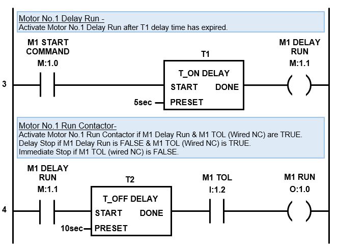
The third rung works the same as the delay ON timer example above, except we replace the M1 RUN output with internal variable M1 DELAY RUN. This enables us to create a fourth rung and trigger a delay OFF timer in order to create the delay stop.
When the PLC scan hits the third rung it comes across the symbol, M1 START COMMAND . If the motor is running this symbol will be TRUE and the logic will flow to the next symbol, T1 (TON timer for the start siren). Timer T1 starts timing and after 5 second timer T1 DONE output goes TRUE. The logic then flows to M1 DELAY RUN output and it too goes TRUE.
The scan then jumps to the fourth rung where the M1 DELAY RUN symbol is TRUE allowing logic flow to timer T2 (delay OFF timer). When the TOFF timer T2 START input is TRUE its done output also goes TRUE.
The logic then flows to the next symbol M1 TOL input which is TRUE, if the thermal overload input is healthy, and in turn to the M1 RUN output which also goes TRUE. Motor No.1 will start running.
From here the scan will happily cycle through the logic and the motor will continue running until the stop button is pressed. If the M1 STOP input is triggered the logic flow in the first rung will be broken causing M1 START COMMAND output to go FALSE and unlatch.
The scan then moves to the second rung. If the M1 START COMMAND symbol is FALSE it will again break the logic flow, which is of no consequence because the siren is already OFF.
Then the scan will move to the third rung where the M1 START COMMAND symbol is FALSE. This breaks logic flow to both the T1 TON delay timer and M1 DELAY RUN output and they change state to FALSE.
As the scan moves to the fourth rung, M1 DELAY RUN symbol is now FALSE which will break logic flow to T2 timer. When the T2 timer START input changes state to FALSE the timer starts timing.
After 10 seconds has lapsed the timer DONE output changes state from TRUE to FALSE and logic flow is broken to M1 RUN output which also changes to FALSE. Hence, the motor experiences a 10 second delay stop.
Now, if the thermal overload trips, then the motor is overheating and we need an immediate stop. In this case the M1 TOL input, in the first rung, will go FALSE and unlatch the M1 START COMMAND.
When the scan reaches the fourth rung the M1 TOL input will be FALSE which will break the logic flow to M1 RUN output, disabling the delay stop function and causing an immediate motor stop.
3) ON & OFF PLC Timer : Light Flasher.
On and OFF timer logic is often referred to as flasher ladder logic. Why? Because, among other things, we can use it to make a light flash on and off and blink at different rates.
The ON and OFF ladder logic timer is basically a two-step cyclic sequence based on time. Both the ON and OFF times are adjustable. The preset time of the first timer dictates the OFF time and the preset time of the second timer dictates the ON time.
The flashing light PLC timer with two adjustable ON delay timers can be set with an uneven blinking cycle if required. Another timer example with two different cycle times is a plastic shredder that runs cyclically to reduce jamming by going forward for 60 seconds and then reversing for 5 seconds.
A PLC flasher timer utilizes a timer loop in the ladder logic program. Two ON delay timers are programmed in the ladder diagram on consecutive rungs, one after the other. The output of the first timer triggers the second timer, the output of the second timer resets both timers, and the cycle repeats.
For our flashing light ladder logic example let us build on the previous motor control ladder diagram example and add a flashing warning light that activates after the siren has finished and the motor starts running. In this example the light blinking rate is set to 1 second ON and 1 second OFF.
In this case we would use the M1 RUN output (from the example above) to trigger our timing circuit.
We need to add an extra output, internal variable and two ON delay timers to our variable declarations.
Below is the list of required inputs, no change ….
| NAME | ADDRESS | TYPE | COMMENT | PLC WIRING |
| M1 START | I:1.0 | BOOL | Motor No.1 Start Push Button | Normally Open |
| M1 STOP | I:1.1 | BOOL | Motor No.1 Stop Push Button | Normally Closed |
| M1 TOL | I:1.2 | BOOL | Motor No.1 Thermal Overload | Normally Closed |
Next let’s add the extra light output, M1 LIGHT….
| NAME | ADDRESS | TYPE | COMMENT | PLC WIRING |
| M1 RUN | O:1.0 | BOOL | Motor No.1 Run | Normally Open |
| M1 SIREN | O:1.1 | BOOL | Motor No.1 Siren | Normally Open |
| M1 LIGHT | O:1.2 | BOOL | Motor No.1 Warning Light | Normally Open |
We need an extra internal variable for the timers, M1 LIGHT TIMER….
| NAME | ADDRESS | TYPE | COMMENT |
| M1 START COMMAND | M:1.0 | BOOL | Motor No.1 Start Command |
| M1 DELAY RUN | M:1.1 | BOOL | Motor No.1 Delay Run |
| M1 LIGHT TIMER | M:1.2 | BOOL | Motor No.1 Warning Light Timer |
Finally let’s add the two extra ON delay timers, T3 and T4….
| NAME | ADDRESS | TYPE | COMMENT |
| T1 | T1 | TIMER | Motor No.1 Start Delay Timer |
| T2 | T2 | TIMER | Motor No.1 Stop Delay Timer |
| T3 | T3 | TIMER | Motor No.1 Light Flasher Off Timer |
| T4 | T4 | TIMER | Motor No.1 Light Flasher On Timer |
Check out the PLC ON & OFF timer ladder diagram which we can tack onto the bottom of the previous ladder diagram….
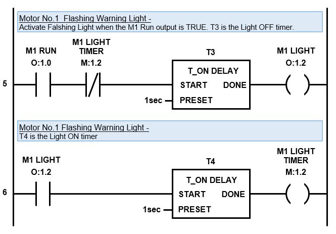
When the PLC scan hits the fifth rung it comes across the M1 RUN output symbol. If the motor is running this symbol will be TRUE and the logic will flow to the next symbol, M1 LIGHT TIMER.
The M1 LIGHT TIMER symbol is normally closed (NC) and will be FALSE because timer T4 (on the sixth rung) is not active and done. This means the M1 LIGHT TIMER symbol allows logic flow to timer T3.
Timer T3 starts timing and after 1 second timer T3 DONE output goes TRUE and the logic flows to M1 LIGHT output and it too goes TRUE.
Then the PLC scan moves to the sixth rung where M1 LIGHT symbol is now TRUE allowing timer T4 to start timing. While timer T4 is timing it’s DONE output is FALSE, therefore the logic flow is broken and M1 LIGHT output is also FALSE.
The scan keeps cycling through the rungs until the 1 second preset time for timer T4 has expired and then timer T4 DONE output on rung six goes TRUE. Then logic flows to M1 LIGHT TIMER output and it too goes TRUE.
When the scan cycles back to the top and moves through to the fifth rung again we notice that M1 LIGHT TIMER symbol has changed state from FALSE to TRUE thus breaking the logic flow and resetting timer T3 and M1 LIGHT output back to FALSE.
As the scan progresses from the fifth to the sixth rung timer the M1 LIGHT symbol at the start of the rung is now FALSE thus breaking the logic flow to the rest of the rung and resetting T4 and M1 LIGHT TIMER output back to a FALSE state as well. Effectively resetting the timer sequence. So when the scan cycles back to the top it starts the timing cycle once again.
The timing cycle will continue until the motor stops running, when the M1 RUN symbol changes state to FALSE.
M1 LIGHT output is used to wire to the flashing light. It will be OFF for T3 time preset (1 second) and ON for T4 timer preset (1 second). The timing cycle will continue until the motor stops running, when the M1 RUN symbol changes state to FALSE.
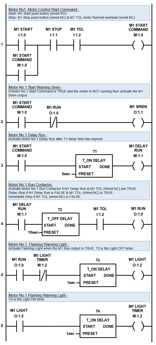
PLC Timer Examples : Complete Ladder Diagram
The Delay Start Warning with Siren, Flasher Timer and Delay Stop timer are my 3 favorite timer examples. I frequently use these example in my day to day ladder logic programming. The complete ladder diagram including all three examples for motor start application is below….
In the next section we’ll discover the four fundamental elements required to structure sequence logic and apply it to automate a real life application.
To go to the next section click here.