Ladder logic is a programming language that is used to program a PLC (Programmable Logic Controller). It is a graphical PLC programming language which expresses logic operations with symbolic notation using ladder diagrams, much like the rails and rungs of a traditional relay logic circuit.
Ladder logic is a fast and simple way of creating logic expressions for a PLC in order to automate repetitive machine tasks and sequences. It is used in a multitude of industrial automation applications. Some industrial automation application examples where PLC ladder logic is used include….
- Material Handling Conveyor System.
- Pallet Packing and Strapping.
- Ball Mill Lubrication System.
- Logistics Package Conveying and Sorting.
- Cement Batching.
- Beverage Bottling and Labeling.
- Hopper and Tank Level Control.
- Air and Liquid Flow and Pressure Control.
In the good ol’ days, machine and process automation was accomplished using a hard wired control system known as relay logic. With the advent of microprocessors and the invention of the PLC, relay logic quickly became superseded by programming languages such as ladder logic.
Why is Ladder Logic Popular?
Ladder logic is the most popular method of PLC programming because it has an easy to use graphics based interface and the programming language resembles an electrical schematic drawing. Engineers, electricians and students find the transition from an electric circuit to ladder logic relatively easy.
When programming ladder logic in a PLC, the graphic, drag and drop nature of ladder diagrams helps you formulate code quickly and easily. Ladder logic also helps you easily trouble shoot your code because you can visually see the flow of logic from the LHS start rail, through the logic symbols and to the RHS end rail.
Compared to text based programming languages, ladder logic programming is a lot easier to use.
Learning the Basics of Ladder Logic
It’s relatively easy to learn the basic concepts of ladder logic programming, even if you don’t have experience with electric circuits. Take comfort in knowing that ladder logic is the quickest and easiest PLC programming language to learn.
In order to help you learn the basics of ladder logic we will cover the following….
- Introduce the ladder diagram.
- Examine the seven basic parts of a ladder diagram.
- Identify the binary and logic concepts used in ladder logic.
- Reveal the hidden ladder logic functions that are automatically built into the structure of the ladder diagram.
- Discover the five fundamental logic functions that are essential to know.
So let’s begin….
What is a Ladder Diagram in a PLC?
A ladder diagram is the symbolic representation of the control logic used for programming of a PLC. Ladder diagrams have horizontal lines of control logic called rungs and vertical lines at the start and end of each rung called rails. It looks just like a ladder, hence the name “ladder diagram”.
There are two main differences between an electrical schematic and a ladder diagram:
- The control logic in an electrical schematic is represented using components whereas in a ladder diagram symbols are used.
- The control logic execution in an electrical schematic is as per the operation of an electrical circuit whereas in a ladder diagram it relies on the methodical nature of the PLC scan
Why is a ladder diagram used for PLC programming?
Ladder diagrams are used to formulate PLC logic expressions in graphical form. They use symbols to represent conditional, input and output expressions. Ladder diagrams are similar to relay control circuits and are used due to their ease of programming compared to text based programming languages.
Early control system designers were accustomed to relay logic control circuits and ladder diagrams closely mimic these. They preferred to use ladder diagrams for PLC programming instead using text based programming languages of the day like C, BASIC, Pascal and FORTRAN.
Factory maintenance staff already understand how to read relay control circuits. They can use their knowledge of relay control circuits to help troubleshooting control system problems that implement PLC programming with ladder diagrams.
Ladder Diagram (LD) is the official name given in the international PLC programming standard IEC-61131. But, these days the terms ladder diagram, ladder logic diagram, ladder drawing, ladder control, ladder circuit, control logic diagram and logic diagram (to name a few) are all used to describe relay logic circuits and ladder logic programming.
So don’t get too caught up in the specific definition of each of these expressions, they kind of generally all mean the same thing. At the end of the day most people will know what you are talking about anyway. Personally, I use the term ladder logic for PLC programming and relay logic for relay control circuits.
To access the body responsible for maintaining the IEC-61131 standard please click here.
How to Draw Ladder Logic Diagrams?
Ladder logic diagrams are drawn in a similar way to relay logic circuit. They use rails and rungs to create the logic framework. The logic operations are drawn in using symbolic notation.
The rails in a relay logic circuit represent the supply wires of a relay logic control circuit. However, in ladder diagrams, the rails represent the start and end of each line of symbolic code.
The rungs in a relay logic circuit represent the wires that connect the components together. However, in a ladder diagrams, the rungs represent the logic flow through the symbolic code.
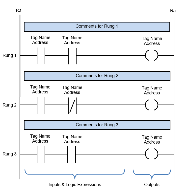
When implementing a ladder logic program in a PLC there are seven basic parts of a ladder diagram that critical to know. They are rails, rungs, inputs, outputs, logic expressions, address notation/tag names and comments. Some of these elements are essential and others are optional.
To help understand how to draw ladder logic diagrams the seven basic parts of a ladder diagram are detailed below…..
- Rails – There are two rails in a ladder diagram which are drawn as vertical lines running down the far most ends of the page. If they were in a relay logic circuit they would represent the active and zero volt connections of the power supply where the power flow goes from the left hand side to the right hand side.
- Rungs – The rungs are drawn as horizontal lines and connect the rails to the logic expressions. If they were in a relay logic circuit they would represent the wires that connect the power supply to the switching and relay components. Each rung is numbered in ascending sequential order.
- Inputs – The inputs are external control actions such as a push button being pressed or a limit switch being triggered. The inputs are actually hardwired to the PLC terminals and represented in the ladder diagram by a normally open (NO) or normally closed (NC) contact symbol.
- Outputs – The outputs are external devices that are being turned on and off, such as an electric motor or a solenoid valve. The outputs are also hardwired to the PLC terminals and are represented in the ladder diagram by a relay coil symbol.
- Logic Expressions – The logic expressions are used in combination with the inputs and outputs to formulate the desired control operations.
- Address Notation & Tag Names – The address notation describes the input, output and logic expression memory addressing structure of the PLC. The tag names are the descriptions allocated to the addresses.
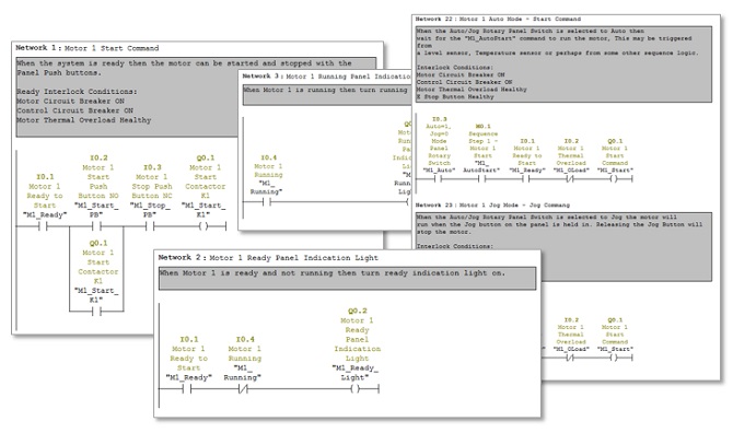
- Comments – Last but by not least, the comments are an extremely important part of a ladder diagram. Comments are displayed at the start of each rung and are used to describe the logical expressions and control operations being executed in that rung, or groups of rungs. Understanding ladder diagrams is made a lot easier by using comments.
How Does Ladder Logic Work?
Ladder logic works in a similar way to relay logic, but without all the laborious relay control wiring. In simple terms, the field input and output devices are wired directly to the PLC and the ladder logic program decides what outputs to activate, depending on the status of the input signals.
Just like relay logic, ladder logic has supply rails, relay coils, relay contacts, counters, timers, PID loop controllers and much more. The difference is that with relay logic the logic expressions are created with relay control circuits. This can amount to large amounts of relays and wiring. However, with ladder logic the logic expressions are programmed in the PLC. So, the only wiring required is for the input and output devices.
How to Read Ladder Logic?
Ladder logic is read from the left hand rail to the right hand rail and from the first rung to the last rung. In short – LEFT TO RIGHT AND TOP TO BOTTOM. The rungs contain input symbols that either pass or block the logic flow. The result of the rung is expressed in the last symbol, known as the output.
To start reading ladder logic we need to know some basic binary concepts, how they apply to ladder logic, how ladder logic is executed and the basic logic functions that are built into each rung. Let’s begin….
The Binary Concept Applied to Ladder Logic
Microprocessors, like the ones found in PLCs and personal computers operate on the binary concept. You’ve probably heard of the term ‘binary’. It refers to the principle that things can be thought of in one of two states. The states can be defined as:
True or False
1 or 0
On or Off
High or Low
Yes or No
Microprocessors love binary….. 10101011101000111010001010100010100100101010010011.
I don’t know about you, but my head hurts just looking at that! Luckily ladder logic uses symbolic expressions and a graphical editor for writing and reading ladder diagrams making it easier for us mere humans to comprehend.
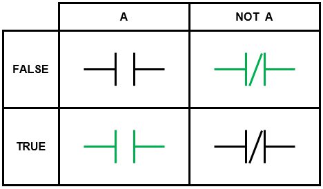
In a PLC, binary events are expressed symbolically using ladder logic in the form of a normally open contact (NO) and normally closed contact (NC).
The normally open contact (NO) is TRUE when the event is active and FALSE when the event is NOT active. While the normally closed contact (NC) is FALSE when the event is active and TRUE when the event is NOT active.
Let me explain NO and NC contacts a little further …..
Normally Open Contact (NO) in Ladder Logic
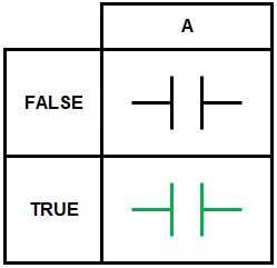
The event associated with a normally open contact (NO) can be TRUE or FALSE. When the event is TRUE then it is highlighted green and the logic flow can move past it to the next logic expression. Just like the current flow in an electric circuit when a switch is turned on.
Let’s call a certain PLC input event ‘A’. This PLC input event could be something like a button being pushed, a limit switch being activated or a temperature switch being triggered.
PLC input event ‘A’ follows the binary concept and has one of two states, TRUE or FALSE. The ladder logic truth table for a normally open contact (NO) which denotes PLC input event ‘A’ is shown below….
Normally Closed Contact (NC) in Ladder Logic
The event associated with a normally closed contact (NC) can be TRUE or FALSE. The result of the normally closed contact (NC) is basically the opposite state of an event that occurs. So, if PLC input A is FALSE the result will be TRUE. And vise versa when PLC input A is TRUE the result will be FALSE.
The normally closed contact (NC) is considered to be a ladder logic NOT function. It is sometimes referred to as reverse logic. Check out the truth table below….
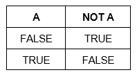
If we translate a NOT function into a ladder logic diagram we express it symbolically in the form of a normally closed contact (NC) as seen in ladder logic truth table shown below….
How Ladder Logic is Executed?
In order to successfully read ladder logic we need a basic understanding of how a PLC works and how ladder logic is executed in a PLC. You see, the PLC follows a certain execution procedure and if not adhered to it can lead to the ladder logic being read incorrectly.
Ladder logic works in a similar way to relay logic, but without all the laborious wiring. It has supply rails, relay coils, relay contacts, counters, timers, PID loop controllers and much more. In simple terms, all the field input and output devices are wired to the PLC and the ladder logic program decides what outputs to trigger depending on the status of the input signals.
In basic terms, PLCs execute ladder logic by first reading all the input states and storing them into memory. Secondly, scanning through and evaluating each rung of ladder logic, from left to right and top to bottom. Lastly, at the end of the scan, the resultant logic is executed and the outputs are written to.
Ladder Logic Basic Functions
In a ladder diagram the normally open (NO) and normal closed (NC) contacts merely tell us what state an event is in, TRUE or FALSE. On their own they cannot decide what action to take to automate something.
We need binary’s best friend ‘logic’ to help out.
Logic is the ability to decide what action needs to be taken depending on the state of one or more events. We use the binary and logic concepts every day in our own lives. For example, if I feel cold then I put my sweater on, but if I feel hot then I take my sweater off.
Binary concept – Cold or Hot, Sweater On or Sweater Off.
Logic concept – IF, THEN logic functions.
Binary Logic in action!
The binary and logic concepts are what makes ladder logic work. The hidden key to unlock your understanding of how ladder logic works is: The logic functions in ladder logic are automatically built into the structure of the ladder diagram.
Let me show you……
Ladder Logic IF, THEN Functions
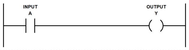
Let’s take a real world event, allocate it to a normally open contact (NO) and call it ‘A’. In ladder logic the real world events are defined as PLC inputs.
Now, let’s call the result of the logic function ‘Y’. In ladder logic the result of a rung logic function is defined as a PLC output.
When we take these two fundamental elements and insert them into a rung in a ladder diagram we get your first line of code!
It’s equivalent to “Hello World” in text based programming languages…..
Now, let’s expose the hidden inbuilt functions by highlighting them in blue in order to illustrate the relationship between the ladder diagram rung structure and its inbuilt IF, THEN functions….
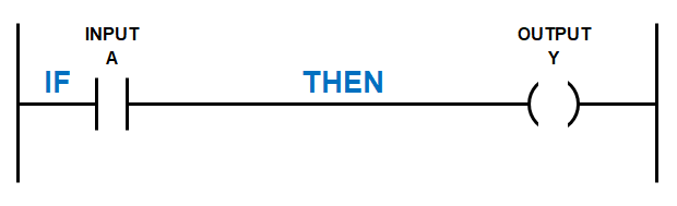
We can write out the logic expression in the above as rung as IF A THEN Y.
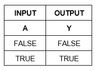
Because PLC input A follows the binary concept it has two possible states, TRUE or FALSE. Therefore it results in two possible logic iterations:
IF A = FALSE THEN Y = FALSE
IF A = TRUE THEN Y = TRUE
We also can express this in a truth table….
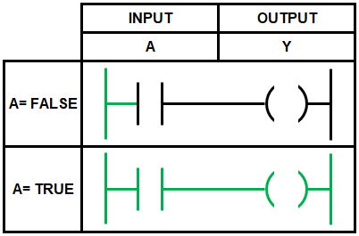
If we translate this into a ladder logic diagram we express it symbolically in the form of a normally open contact (NO) for the input and a relay coil for the output. Remember the logic flow is from left to right and follows the same concept of current flow in an electric circuit.
The ladder logic truth table is shown below….
Ladder Logic AND Function
The AND function examines multiple PLC inputs and has one resulting output. If we translate an AND function into a ladder diagram we can express it symbolically in the form of two PLC inputs A and B using normally open (NO) contacts and a PLC output Y using a relay coil.
They are all connected in line, just like a series connection in an electric circuit. This time we have also highlighted the hidden AND function to illustrate the relationship between the ladder logic functions and the ladder diagram rung structure….
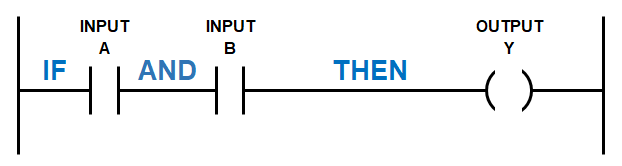
We can write out the logic expression above as IF A AND B THEN Y.
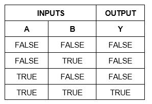
The AND function examines if all the PLC inputs are TRUE, then the corresponding result is also TRUE. However if any one of the PLC inputs is FALSE then the corresponding result is also FALSE.
Because PLC input A and B follows the binary concept and are part of the AND function there are four possible logic iterations. Check out the truth table below….
The number of logic iterations increases with the number of PLC inputs (2PLC Inputs). But that doesn’t matter too much with the AND function because the result can only be TRUE if all the PLC inputs are TRUE.
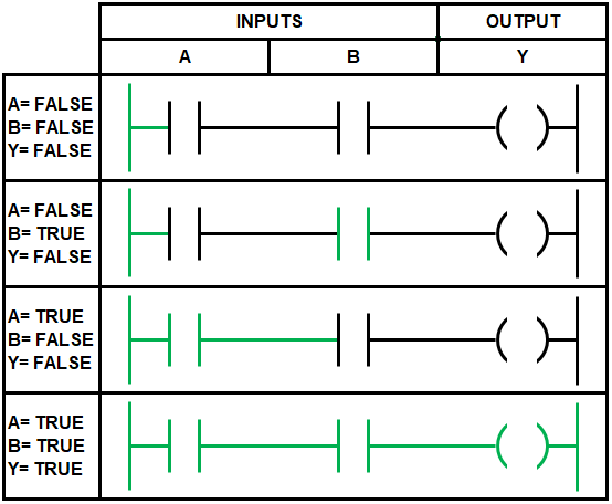
If we translate an AND function into a ladder logic truth table we get the table below….
Ladder Logic OR Function
The OR function examines multiple PLC inputs and has one resulting output. If we translate an OR function into a ladder diagram we can express it symbolically in the form of two PLC inputs A and B using normally open contacts (NO) and a PLC output Y using relay coil.
The inputs are placed in the rung in what is known as a branch. This is the equivalent of a parallel connection in an electric circuit. The output is then connected in line with the rung. This time we have also highlighted the hidden OR function when we create a branch (parallel connection) with PLC input B across PLC input A….
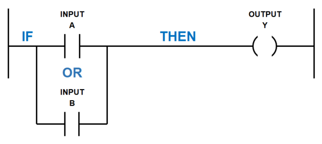
We can write out the logic expression above as IF A OR B THEN Y.
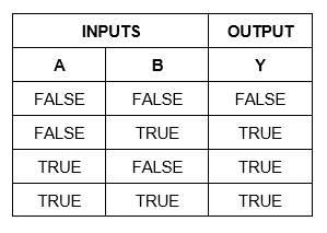
The OR function examines if any of the PLC inputs are TRUE, then the corresponding result is also TRUE. However, all the PLC inputs must be FALSE in order for the corresponding result is also be FALSE.
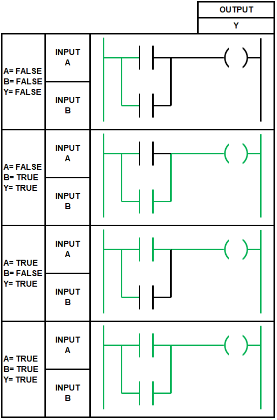
Because PLC input A and B follows the binary concept and are part of the OR function there are four possible logic iterations. Check out the truth table below….
Remember, the number of logic iterations increases with the number of PLC inputs (2PLC_inputs). But that doesn’t matter too much with the OR function because the result can be TRUE if any of the PLC inputs are TRUE.
If we translate an OR function into a ladder logic truth table we get the table below….
Wow, you’ve flown through the binary and logic functions. Remember…
For basic ladder logic programming we express binary events using normally open contacts (NC) and normally closed contacts (NC).
The five basic, yet essential, logic functions in ladder logic are:
- NOT
- IF
- THEN
- AND
- OR
You may be surprised, but when we utilize all these functions in our ladder logic programming we will be able to program the majority of automation control requirements.
Well done! You now have a handle on the basics of ladder logic.
In the next section we will jump straight into the most common symbols that you can’t do without when ladder logic programming. We’ll also examine their operation and outline some of their most popular uses. To go to the next section click here.
If you’d like to learn the basics of a PLC (Programmable Logic Controller) then click here.