PLC sequencer logic is an essential component to have in your quiver of ladder logic sample code.It forms the backbone to the majority of processes for industrial automation. Applications that require sequencer logic include conveyor systems, palletizing machines, batching plants, packaging machines, storage and retrieval systems and the list goes on and on.
A sequence in industrial automation is merely a series of actions required to be taken to achieve a specific outcome arranged in an orderly fashion.
The basis to develop a sequence in ladder logic is to use sequence steps.
It’s a good idea to declare the sequence steps as internal variables, which in turn can be used multiple times in the program if required.
PLC Sequence Steps
To illustrate how sequence steps are derived for PLC Sequencer Logic let’s look at the sequence of events required for a common household task, brushing your teeth….
- Grab your toothbrush.
- Grab your toothpaste.
- Put some toothpaste on the toothbrush.
- Put the toothbrush in your mouth.
- Brush your teeth with the toothbrush for two minutes.
- Remove the toothbrush from your mouth.
- Rinse your mouth out with water.
- Rinse your toothbrush with water.
- Put your toothbrush away.
To automate an industrial process with a sequence we use the same concept. The complexity of the sequence ladder logic program will depend on the specific process outcomes required.
Even with the tooth brushing example above some of the steps can be broken down even further.
For example step 3 can be broken down into three steps with significantly more detail….
3a) Position the toothpaste nozzle at the far end of the toothbrush head.
3b) Squeeze the toothpaste while moving it lengthwise along the toothbrush head until it reaches the end of the toothbrush head.
3c) Stop squeezing the toothpaste and place it in the toothpaste holder.
Types of PLC Sequencer Logic
A sequence can either be cyclic or linear.
A cyclic sequence moves through the sequence steps and when the final step is completed the sequence automatically restarts from the beginning and keeps repeating the sequence until a stop command is initiated.
A linear sequence moves through the sequence steps and when the final step is completed stops and sits idle until a start command is re-issued manually by the operator.
The 4 Essential Elements of PLC Sequencer Logic
There are various ways to structure the sequence ladder logic but as a minimum it must contain four essential items of code…..
- Sequence start and stop.
- The Sequence steps.
- Sequence step transition conditions.
- The outputs that initiate actions.
Once we know the basic sequence ladder logic structure we can modify it to suit the process requirements. We can create multiple sequences, parallel sequence branches and add logical expressions and timers to help control it.
The sequence start, stop and steps require latching logic using either hold in logic or Set (latch) Reset (Unlatch) symbols.
If you don’t know what hold in logic and Set/Reset symbols are then click here.
PLC Sequencer Logic Example
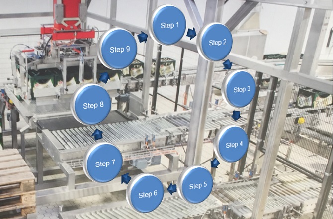
Let’s follow on from our motor control example used earlier and define a sequence utilizing a motorized trolley.
The trolley runs forward to a certain position. Accepts a pallet of produce from an automated crane. Then reverses back to it’s starting position ready to be unloaded by a forklift operator and put into the back of a truck for transportation.
The motorized trolley has a limit switch for the unloading and loading positions so it can stop in the correct place.
It has a sensor to detect if there is a pallet on the trolley.
It also has a sensor to detect if the loading area is clear and is safe for the motorized trolley to start moving.
To activate the sequence the operator decides if the trolley is unloaded and safe to run, then pushes the start push button.
When the sequence completes a cycle it stops and waits for the operator to push the start button again. This is a linear sequence with a start and end point.
After the sequence is complete it must be re-initiated manually by an operator in order for the sequence to restart.
Having said that, we just as well could have chosen to do an automatic cyclic sequence. This is easily done at the last step by re-activating the first sequence step instead of ending the sequence. We will also need to add some extra conditional logic to replace the operators manual start operation.
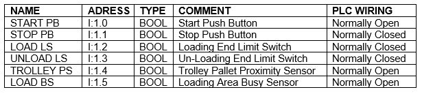
Below is the list of required inputs that need to be declared …..
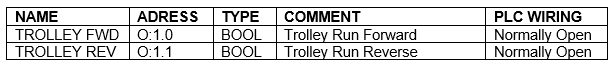
Next let’s declare the outputs…..
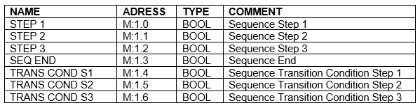
We also need to declare the following internal variables…..
The sequence logic diagram below is a basic linear sequence with three steps that ends after the third step transition conditions are met….
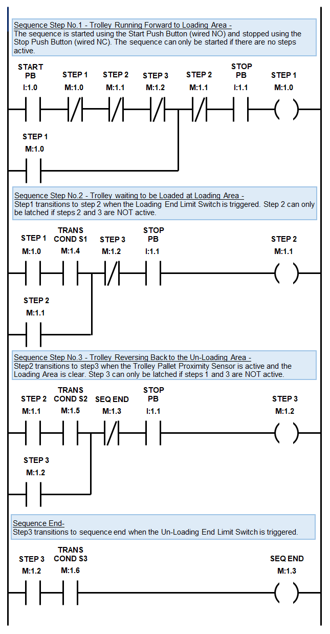
The transition conditions that enable the steps to progress to the next step and the actual sequence steps are all declared as internal variables.
In this way we can take the conditional logic out of the sequence logic rungs to de-clutter it and make it easily readable.
We should place the transition conditional logic before the sequence logic to allow for the PLC scan going from top to bottom….

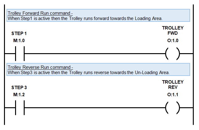
Lastly we need some logic to trigger the PLC outputs to make the trolley move.
There’s no need to use additional latching logic for the motor start because we are utilizing the sequence step latching logic.
We should place logic that triggers the outputs after the sequence logic to allow for the PLC scan going from top to bottom.
Advanced Sequence Ladder Logic Programming
Even though this example is a simple control sequence it provides the backbone for more complex additions.
Some examples of additional features include….
- Auto and manual modes so that individual components can be operated in case of failures and maintenance.
- Sequence status and indication lights and sirens.
- A stopping sequence and/or emergency stop function can also be added if required.
- Conditional logic that needs to be met before the sequence can be started.
- Sequence pause logic to remember the last step before the sequence was stopped, so that the sequence can resume from where it left off.
- Conditional start logic that decides the step that must be triggered to resume operation.
- Alarm and fault logic to capture failure of equipment.
It’s great using hold in logic to latch the sequence steps because all the transition and stopping conditional logic is located in the same area.
When we encounter more complex processes then using hold in logic for our sequence steps can become difficult because we are limited to using only one output.
Using multiple output symbols with the same variable declaration is a recipe for disaster.
We don’t want to do this because the output symbol may be overwritten inadvertently during the PLC scan causing haphazard like behavior.
If the ladder diagram complexity is high then we can latch and unlatch sequence steps using the Set (Latch) and Reset (Unlatch) symbols.
These symbols provide a lot more flexibility with the sequence programming, but require extra caution and expertise.
In the next section we’ll provide you with a comprehensive guide to programming ladder logic flip flop’s and toggle logic.
To go to the next section click here.