Experience tells us that once a piece of ladder logic is created that accomplished a specific task it can be re-used in other areas of the program and in other applications as well. So by creating ladder logic programming examples we can speed up or overall programming time.
Constructing a program is then a simple matter of grabbing the appropriate ladder logic programming examples and connecting them in an orderly fashion.
Let’s take a look at some very simple, but extremely important ladder logic programming examples…
Latching in a PLC
Latching is one of the most important pieces of ladder logic programming that you’ll ever use.
Latching in a PLC refers to ladder logic code that simulates the operation of a latching relay. It requires two inputs and an output. The output is latched (set TRUE) with one of the inputs. The output is unlatched (reset to FALSE) with the other input. A momentary pulse can be used for the inputs.
This can be achieved with two methods….
- Set and Reset instructions: In an Allen Bradley PLC they are called Latch and Unlatch instructions. These instructions simulate the function of an electro-mechanical latching relay. Advantages include flexibility in programming because the Set (Latch) and Reset (Unlatch) symbols do not need to be in the same rung. The disadvantage is that debugging can become more difficult because the Set (Latch) and Reset (Unlatch) symbols may be scattered throughout the program.
- Latching logic: Quite often “latching logic” is referred to as “hold in logic”. It’s ok to interchange the terms. The advantage of latching logic is that troubleshooting is easier because the symbols used are all in the same rung. The disadvantage is that there is some inflexibility in programming because latching logic requires all the symbols to be on the same rung and may even overflow to the next rung. This can be restrictive in some cases.
Simple applications requiring a latch are well suited to use latching logic.
But when it comes to more complex applications the use of Set (Latch) and Reset (Unlatch) symbols may be required.
Sometimes it just comes to personal preference.
Latching in a PLC requires at least one input to set the latch (Input A), one input to reset the latch (Input B) and one output to store the latch state (Output Y).
The inputs that set and reset the latch are usually momentary pulses. A great example of a device that can provide a momentary pulse to a PLC input is a push button.
Ladder Logic Latch with SET & RESET Symbols
Let’s start with the Set (Latch) and Reset (Unlatch) logic. Remember Allen Bradley PLC’s use Latch and Unlatch symbols.
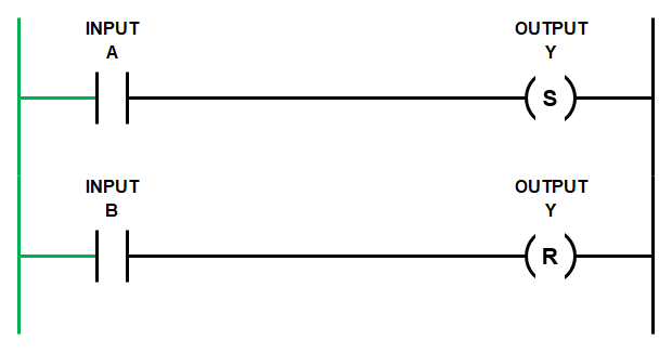
The rungs below show the basic code.
When both Input A and Input B are FALSE then the state of Output Y does not change. If Output Y is FALSE then it stays FALSE….
If Input A goes TRUE momentarily then the SET symbol changes the state of Output Y to TRUE.
Then, after subsequent scans, if Input A changes state to FALSE it does not affect the state of Output Y. In other words, Output Y is latched TRUE…
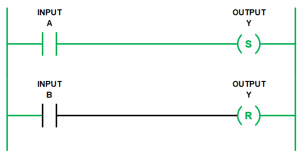
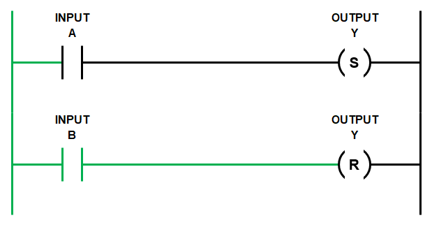
Only when Input B changes state to TRUE will the RESET symbol change the state of Output Y back to FALSE. In other words, Output Y is now unlatched….
Remember the PLC scan runs from left to right and from top to bottom.
So if both Input A and Input B are TRUE at the same time, then in the ladder diagram above the first rung is evaluated and Output Y is set TRUE.
But, then the second rung is evaluated and Output Y is set FALSE.
Once the scan reaches the end of the entire program it will execute the state of Output Y as FALSE.
Ladder Logic Latch with Hold In Logic
Using hold in logic to achieve latching has a similar outcome to using Set (Latch) and Reset (Unlatch) symbols.
But with hold in logic both Input A and Input B are on the same rung as Output Y. Also, the way in which the latch is SET and RESET is done differently.
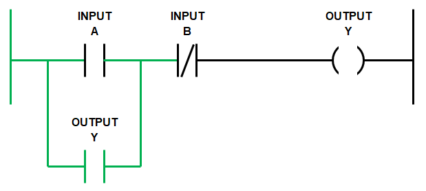
Notice that Input B is a normally closed (NC) contact symbol and Output Y is used twice and branched (or in parallel with Input A).
Ponder that thought for a second, let’s continue….
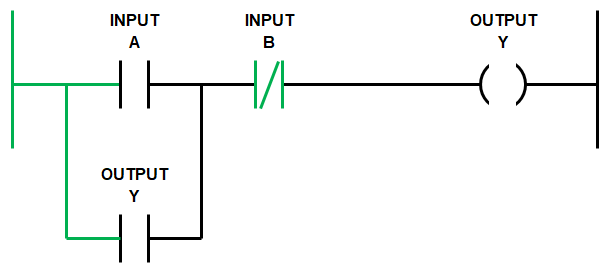
Remember the scan goes from left to right and top to bottom.
So the scan starts from the left hand side of the rung and moves right to Input A.
If Input A goes TRUE and Input B is FALSE then Output Y goes TRUE….
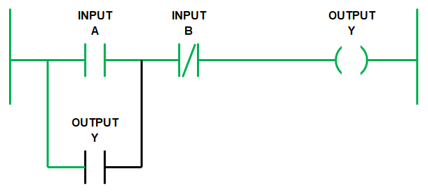
The scan continues on with the rest of the program and it cycles back to the rung.
Previously Output Y had changed state to TRUE, so now Output Y that is in a branch across Output A, also goes TRUE and there is no other change….
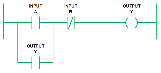
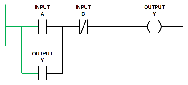
When the scan cycles back again from the top, if Input A goes FALSE, with Input B still FALSE, then Output Y stays TRUE.
This is because Output Y is held in by itself using the branch across Input A.
Notice that the logic flows from the left hand side rail through the Output Y branch and then through Input B to Output Y at the right hand side rail. Pretty cool…..
Once we have triggered the hold in logic using Input A, Output Y will remain latched even if Input A goes FALSE.
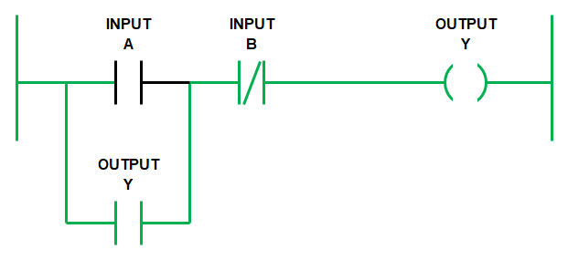
Output Y will remain latched TRUE until Input B goes TRUE. Because Input B is a normally closed (NC) contact symbol, when it goes TRUE, the logic flow is blocked and Output Y goes FALSE. Thus releasing the latch.
Remember the NC contact symbol works like a NOT statement, it’s reverse logic….
So, when the scan cycles back again from the top then Output Y, branched across Input A, also goes FALSE….
Once Input B returns to the FALSE state we are back at the start, ready to initiate the latch again.
We can write out the logic expression above as…
IF (INPUT A OR OUTPUT Y) AND NOT (INPUT B) THEN OUTPUT Y.
Hold in logic is great to use because it simplifies your code. It enables us to place all the conditions that initiate and release latch in the same rung. This makes it easier to read and troubleshoot.
PLC Motor Control
Ladder logic for motor control can be accomplished using hold in logic. Remember it’s ok to also call it latching logic.
Simple ladder logic for motor control using push button start stop logic includes a start button, stop button, motor thermal overload and motor run contactor.
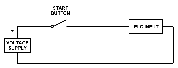
When we wire up the inputs to the PLC the start push button input is wired normally open (NO). So when the start button is pushed the PLC input changes state from FALSE to TRUE…
But the stop push button and thermal overload are always wired normally closed (NC). So when the stop button is pushed it changes from CLOSED to OPEN. In turn the PLC input changes state from TRUE to FALSE….
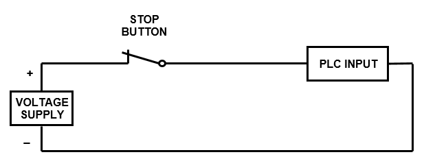
In fact the rule of thumb is that any device that is required to stop the motor should be wired normally closed (NC), to make it “fail safe”.
The most common failures are wire break, device failure or PLC input failure.
Wiring the stop push button normally closed (NC) is done because when a failure occurs in the PLC input circuit it will, more often than not, lead to an open circuit which changes the state of the PLC input from TRUE to FALSE.
However, if we wire the stop PLC inputs as normally open (NO) and a failure occurs then the state of the PLC input does not change. It stays FALSE, even if the stop button is pressed, because there is an open circuit in the connection to the PLC input.
So if there is no change in state, we cannot tell the motor to stop in our ladder logic program. This is really bad!!!
So for any PLC input that is intended to stop the motor we need to..…
WIRE THE MOTOR STOP SIGNALS NORMALLY CLOSED AND USE A NORMALLY OPEN SYMBOLS IN THE PLC.
Now that we’ve grasped the concept of the fail safe stop input let’s move on to the motor control ladder logic programming example.
Motor Control Ladder Diagram
First up let’s list the required inputs and outputs for our motor control ladder diagram.
PLC manufacturers use different memory address allocation so the input output allocations used here are arbitrary address.
Below is the list of required inputs …..
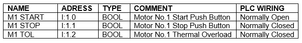
Next let’s list the required outputs…..

The ladder logic programming example uses the M1 START push button input to activate the M1 RUN output.
The M1 RUN output is used a second time to latch the M1 RUN output.
Both M1 STOP and M1 TOL are wired normally closed (NC) to the PLC inputs and thus need to be configured as normally open (NO) symbols in the logic.
So when either stop is activated the logic flow is broken and the latch is reset….
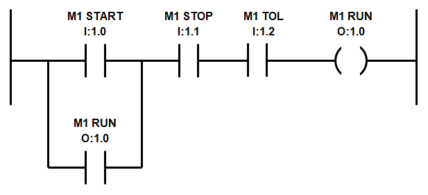
Remember, we must wire M1 Stop and M1 TOL using normally closed (NC) contacts to the PLC inputs to make it “fail safe” and for this motor control ladder diagram to work.
If you don’t know what the heck I’m talking about you’ve probably skipped straight to the motor control ladder diagram. Please….Go back and read the section above to get full bottle on latching logic…..It’s important!
PLC Wiring Basics
If you are still a little confused about the different PLC wiring and ladder diagram symbol combinations and their different logic states then….DON’T PANIC!
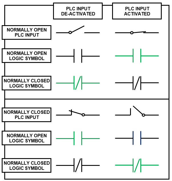
To help out we’ve developed a nifty table which displays the different combinations of PLC digital input wiring and ladder logic symbols that can be used.
Further more, it outlines the logic state each of the ladder logic symbols depending on whether the PLC input is activated or de-activated. When the symbol is BLACK it’s state is FALSE and when the symbol is GREEN it’s state is TRUE.
In the next section we’ll build on our newly discovered knowledge by exploring different PLC timer instructions, their PLC symbols, timing diagrams and operational description from various manufactures and brands.
To go to the next section click here.