
The PLC timer simulates the function of traditional timer relays. Initially, timer relays were utilized in relay logic circuits and were mechanical in nature. Over time, the mechanical timer relays were replaced by electronic timer relays and now, in modern times, they reside in the PLC as software timers.
A PLC timer is an instruction used in ladder logic programing. When added to a ladder diagram it introduces a time delay when a specific event occurs. In its most basic form a PLC timer has a start input, a preset time input and a done output.
It is important to understand that a PLC timer instruction introduces a time delay which only affects the execution of the timers outputs. The PLC scan is not directly delayed, it still scans through all the ladder logic rungs as per normal.
How does a PLC timer work? A PLC timer continually monitors its start input for a change in its logic state. When the logic state of the start input changes the timer starts running. After the timer reaches the preset time setting, the done output is triggered.
How is a PLC timer reset? Depending on its type, a PLC timer can be reset in one of three ways. ON-delay timers can be reset by removing the start input. OFF-delay timers and Pulse timers are reset after the preset time expires. Other timers, in fact any timer with a reset input, can be reset at any time by triggering the reset input.
Types of PLC Timers
Different types of PLC timers exist based on how they implement the time delay within the timing instruction. The 3 types of PLC timers, as defined in IEC 61131-3 International PLC Programming Standard, are:
- ON-Delay Timer (TON)
- OFF-Delay Timer (TOF)
- Pulse Timer (TP)
In my experience with ladder logic programming I have actually come across 11 different types of PLC timers from various PLC brands, they are:
- ON Delay Timer
- OFF Delay Timer
- Retentive (Accumulating) Timer
- Retentive ON Delay Timer (Siemens PLC)
- Pulse Timer
- Extended Pulse Timer
- Frequency Timer
- Teaching Timer
- Dual Timer
- Multi Output Timer
- Special Timer
However, not all PLC brands have every timer available for use in their ladder logic programming software. For example some Mitsubishi and Omron PLCs do not have OFF-delay timers. And, as far as I know, the dual timer is unique to Idec PLCs.
Check out the table below which is a comparison of PLC timer instructions that are available in some of the most common PLCs brands….
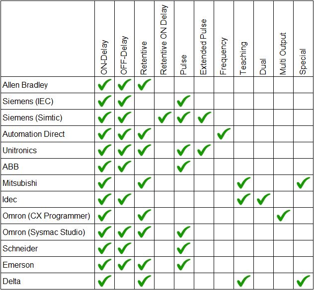
Fun Fact… In the table above you’ll notice that there are 2 types of Siemens timers, Simatic and IEC. The Siemens Step7 programming software uses Simatic PLC timers, but the new Siemens TIA Portal programming software has access to both the Simatic timers and the IEC timers.
Application of PLC Timer Types
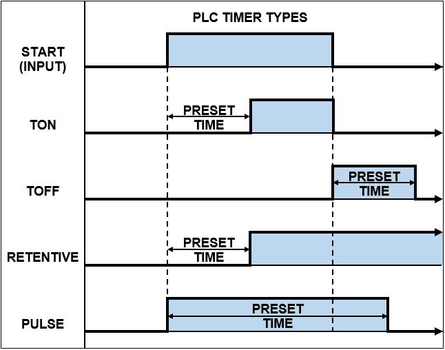
The most common application of PLC timer types are the ON Delay PLC timer, OFF Delay PLC timer, Retentive PLC timer and Pulse PLC timer. Each type uses its time delay and triggers its output in a specific way.
The application of a PLC timer depends on when the time delay is required. If a delay is required after an event changes state to ON, then application of an ON-Delay timer is required. However, if a delay is required after an event changes state to OFF, then application of an OFF-delay timer is required.
Use the chart below to help decide what type of PLC timer to use for your specific application…
PLC Timer Instructions
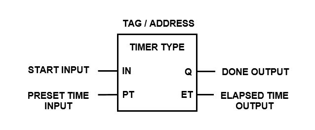
Timer instructions in a PLC have a number of elements which must be defined and/or assigned to an address in order for them to operate correctly. The most common elements that I have come across are shown below….
- PLC Timer Type
- Tag / Address
- Start / Enable (Input)
- Preset Time Value (Input)
- Time Base (Input)
- Reset Input (Input)
- Enabled (Output)
- Done (Output)
- Elapsed / Accumulated Time (Output)
- Remaining Time (Output)
The PLC CPU usually has a memory area assigned specifically for PLC timer instructions. Within the PLC ladder logic instruction set, there’s typically support for a limited number of PLC timers. Generally, the larger the PLC CPU memory, the greater the number of available PLC timers.
Timer instructions in a PLC can vary from one PLC brand to another. Things like the PLC timer symbols, tag, addressing, inputs, outputs, count direction (increment/decrement) and time base (usually 1ms, 10ms, 100ms or 1s) can all be different.
Check out the generic layout of a PLC timer symbol, from IEC 61131-3 International PLC Programming Standard, that is used in ladder logic programming….
Let’s have a look at the different types of PLC timers in a little more detail. We’ll examine all the different PLC timer instructions, their symbols, timing diagrams and operational description from various manufactures and brands. Lets read on….

1) PLC ON Delay Timer
Out of all the different types of PLC timers, the ON delay timer is the one I most commonly use in ladder logic programming. In fact, most of the other timers can be created in ladder logic by using the ON delay timer as the base building block. Luckily most PLCs have created other timing instructions to save us the hassle.
In a PLC the ON delay timer is commonly known as a TON timer. The operation of the ON delay timer is a reflection of its name. You see, the ON Delay Timer (TON Timer) only turns its output ON after a preset time DELAY. In other words, the output is DELAYED before it turns ON.
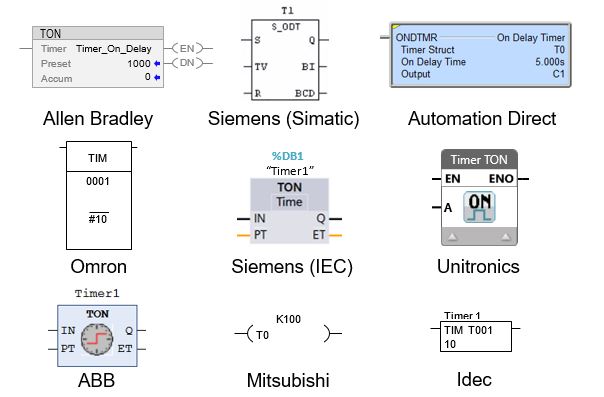
The ON delay timers instruction name, symbol and input/output variables can be expressed in different ways in a ladder logic program depending on which PLC brand you’re using.
For example the TON instruction in a PLC is used in Allen Bradley, Siemens, ABB and Unitronics PLCs. Whereas, the Omron, Mitsubishi, Automation Direct, Delta and Idec PLCs do not use the TON notation for their ON delay timer instruction.
Some examples of ON delay timer instructions, used in different PLC brands, are shown below.…
How the ON Delay Timer Works
The function of an ON delay timer in a PLC is to monitor the occurrence of a certain event (input), add a time delay and then trigger an action (output) after the time delay expires. The time delay is adjustable (preset time input) and the output is reset when the input turns OFF.
The best way to describe the operation of an ON delay timer is by using a timing diagram like the one below…
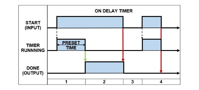
Below is the description of how an ON Delay Timer operates in a PLC. The numbers correspond to the PLC ON Delay Timer – timing diagram above…
- When the START input changes from FALSE to TRUE the PRESET TIME is loaded and the timer begins running. The DONE output remains FALSE while the timer is running.
- After the timer has expired, if the START input is still TRUE, the DONE output is set TRUE.
- The DONE output is reset back to FALSE when the START input goes FALSE.
- If the START input changes from FALSE to TRUE and then back to FALSE before the timer has expired, the DONE output stays FALSE.
2) PLC OFF Delay Timer
The PLC OFF delay timer is the second most commonly used PLC timer that I use in ladder logic programming, only after the PLC ON delay timer.
In a PLC the OFF delay timer is commonly known as a TOF timer. The operation of the OFF delay timer is a reflection of its name. You see, the OFF Delay Timer (TOF Timer) only turns its output OFF after a preset time DELAY. In other words the output is DELAYED before it turns OFF.
In a ladder logic programming the OFF delay timers instruction name, symbol and input/output variables can actually differ depending on the brand of PLC you’re working with.
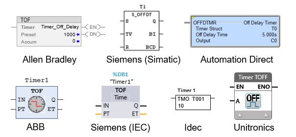
For example the TOF instruction in a PLC is used in Allen Bradley, Siemens, ABB, Unitronics, Schneider and Emerson PLCs. Whereas the Automation Direct and Idec PLCs do not use the TOF notation for their OFF delay timer instruction. In fact, the Omron, Mitsubishi and Delta PLCs do not have an OFF delay timer instruction at all.
Some examples of OFF delay timer instructions, used in different PLC brands, are shown below.…
How the OFF Delay Timer Works
The function of an OFF delay timer in a PLC is to monitor the occurrence of a certain event (input) and immediately trigger an action (output). Then, wait for the input to turn OFF, add a time delay and then reset the output. The delay time is adjustable via the preset time input.
What is the basic difference between a TOF and TON delay timer? The TON timer delays the output from turning ON after the input turns ON. Whereas the TOF timer turns the output ON immediately after the input turns ON and delays the output from turning OFF after the input turns OFF.
A great way to describe the operation of an OFF delay timer is by using a timing diagram like the one below…
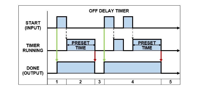
Below is the description of how an OFF Delay Timer operates in a PLC. The numbers correspond to the PLC OFF Delay Timer – timing diagram above…
- When the START input changes state from FALSE to TRUE the DONE output is immediately set TRUE.
- If the START input changes state from TRUE to FALSE, the PRESET TIME is loaded and the timer begins running.
- After the timer expires, the DONE output is reset to FALSE.
- If the START input changes state from TRUE and FALSE multiple times, before the timer has expired, the DONE output remains TRUE and the PRESET TIME is re-loaded each time.
- After the timer expires, the DONE output is reset to FALSE.
3) PLC Retentive (Accumulating) Timer
The Retentive Timer in a PLC works in a similar fashion to the ON Delay Timer because it delays the output from turning ON. But it has some extra features and subtle differences.
In a PLC the Retentive Timer is commonly known as a RTO timer (Retentive Timer ON). The operation of the Retentive Timer is a reflection of its name. You see, it RETAINS the amount of time that the input is active for and only turns the output ON once the total retained time is equal to the preset time value.
A retentive timer is used to record the amount of time that the input is active for and trigger an output after a preset period of time has been reached. A great example is monitoring the accumulated run time hours of a piece of equipment then triggering an alarm when it is time to be serviced.
What happens when the input of a RTO timer becomes false? When the input of a RTO timer becomes false the timer is paused and the current time value is retained. When the input goes true again, the timer resumes from where it left off. Unlike the ON delay timer, the output is not reset when input of an RTO timer becomes false.
How do you reset RTO timer? After the RTO timer is done the output stays ON and can only be reset by triggering the reset input. The reset input has priority and will reset the timer accumulated value back to 0 and the output to OFF. The RTO timer will restart when the start input is ON and the reset input is OFF.
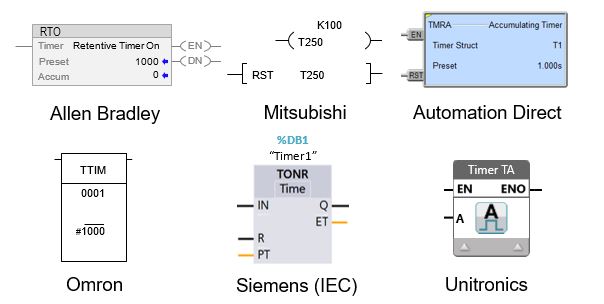
The name, symbols, and input/output variables for Retentive timers can vary within a ladder logic program based on the specific brand of PLC that you’re utilizing. For example the RTO instruction in a PLC is used in Allen Bradley PLCs. However, Siemens (IEC) use TONR, Mitsubishi use T and GE Fanuc (Emerson) use ONDTR.
The PLC Retentive Timer is also known as an Accumulating Timer in some PLC brands. Some examples of PLCs with accumulating timer instructions are Omron with TTIM, Unitronics with TA, Automation Direct with TMRA instruction. Whether the terminology used is retentive timer or accumulating timer their operation is essentially the same.
Some examples of Retentive timer instructions, used in different PLC brands, are shown below.…
How the Retentive Timer Works
The function of a Retentive timer in a PLC is to monitor the occurrence of a certain event (input), record the amount of time that the input is ON and turn the output ON after the accumulated time reaches the preset time value. The retentive timer can only be restarted by triggering the reset input.
An awesome way to describe the operation of a Retentive timer is by using a timing diagram like the one below…
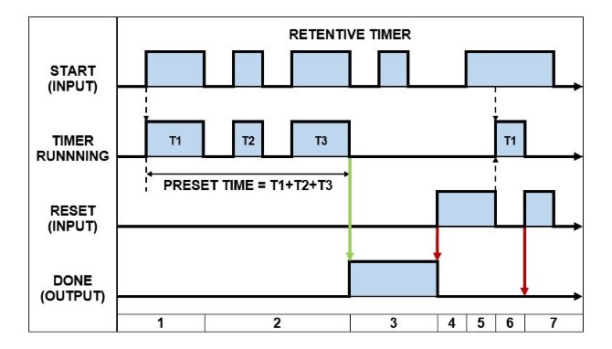
Below is the description of how a Retentive Timer operates in a PLC. The numbers correspond to the PLC Retentive Timer – timing diagram above…
- When the START input changes from FALSE to TRUE and the RESET input is FALSE, the timer PRESET VALUE is loaded and the timer starts running. The DONE output is FALSE at this stage.
- When the START input goes FALSE the timer is stopped, but the accumulated time is retained. When the START input is set TRUE again, the timer resumes running from its last accumulated value, but the DONE output does not change state.
- After the PRESET TIME expires, the DONE output is then set TRUE. Under this condition, if the START input changes state, the DONE output is unaffected.
- When the RESET input goes TRUE, the DONE output is reset to FALSE.
- If the START input and RESET input are TRUE at the same time, the RESET input has priority. Therefore, the DONE output is reset to FALSE and the timer is stopped.
- If the START output is TRUE and the RESET input is FALSE, the PRESET TIME is loaded and the timer begins running.
- If the RESET input is set TRUE, regardless of the state of the START input or timer status, the DONE output is reset to FALSE and the timer is stopped.
4) Retentive ON Delay Timer (Siemens PLC)
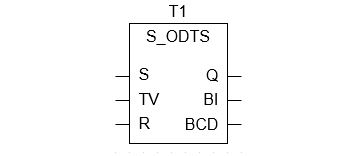
The Retentive ON Delay Timer is unique to the Siemens PLC. In the Siemens PLC the Retentive ON Delay Timer is known as S_ONDTS timer (Retentive ON Delay S5 Timer).
The operation of the Retentive ON Delay Timer (S_ONDTS) is similar to the ON Delay Timer because it only turns its output ON after a preset time DELAY. However, the output can only be reset by triggering the reset input and if the start input is re-triggered, while the timer is running, the timer restarts.
It’s kinda like blending the ON delay and Retentive timers together.
The S_ONDTS timer delays the output from turning ON, but unlike the Retentive timer, does not retain (accumulate) the timer value. Instead it restarts the timer. And unlike the ON delay timer it does not reset when the start input turns OFF. Instead the reset input must be triggered.
In my opinion it should have been called an “ON Delay Extended Timer”.
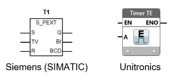
The Retentive ON Delay Timer instruction is expressed in the Siemens PLC as per below….
How the Retentive ON Delay Works
The function of a Retentive ON Delay Timer in a Siemens PLC is to monitor the occurrence of a certain event (input), add a time delay to it, trigger an action (output) and keep the output ON even if the input turns OFF (aha – the output is “retentive”). The output is only reset by triggering the reset input.
A fantastic way to describe the operation of a Retentive ON Delay Timer in a Siemens PLC is by using a timing diagram like the one below…
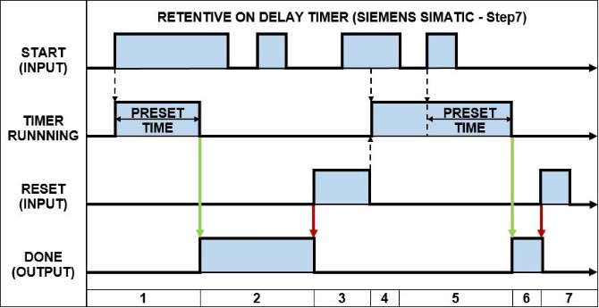
Below is the description of how a Retentive ON Delay Timer operates in a Siemens PLC. The numbers correspond to the PLC Retentive ON Delay Timer (S_ODTS) – timing diagram above…
- When the START input changes from FALSE to TRUE and the RESET input is FALSE, the PRESET TIME is loaded and the timer begins running. The DONE output remains FALSE while the timer is running.
- After the timer has expired, the DONE output is set to TRUE, regardless of the state of the START input.
- When the RESET input goes TRUE, the DONE output is reset to FALSE. If the START input and RESET input are TRUE at the same time, the RESET input has priority. Therefore, the DONE output is reset to FALSE.
- When the START input is TRUE and the RESET input is FALSE, the PRESET TIME is loaded and the timer begins running.
- If the START input transitions from TRUE to FALSE, while the timer is running, the timer is unaffected and keeps running. But if the START input transitions from FALSE to TRUE, while the timer is running, the PRESET TIME is re-loaded and the timer re-starts.
- After the timer has expired, the DONE output is set to TRUE, regardless of the state of the START input.
- The DONE output is reset back to FALSE by setting the RESET input to TRUE.
5) PLC Pulse Timer
The PLC Pulse Timer is another common timer found in PLC programming. It is one of the three PLC timers defined in IEC 61131-3 International PLC Programming Standard.
In a PLC the Pulse Timer is commonly known as a PT timer. The Pulse Timer creates an output PULSE with a pulse duration equal to that of the preset time value. In simple terms, the TP timer output is ON when the timer is running and is OFF all other times.
In a ladder logic programming the Pulse timers instruction name, symbol, and input/output variables can differ based on the brand of PLC you’re using.
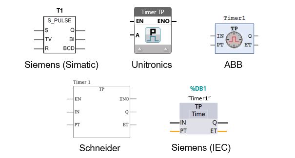
For example the TP timer instruction in a PLC is used in Siemens (IEC), Unitronics, Schneider, ABB and Emerson PLCs. However, Siemens PLCs (Simatic) use the S_PULSE instruction instead. Some PLC brands such as Allen Bradley, Automation Direct,
Mitsubishi, Omron (CX Programmer) and Idec do not have a pulse timer instruction at all.
Some examples of Pulse timer instructions, used in different PLC brands, are shown below.…
How the Pulse Timer Works
How does a pulse timer work? A PLC pulse timer begins to work when its input changes state from FALSE to TRUE. The output is turned ON and the timer starts counting. When the preset time expires the output is turned OFF. Thus, a pulse is created which has a duration equal to that of the timers preset time value.
What is the output of a PLC TP timer? The PLC TP timer output generates a pulse that has a specific time duration. The TP timer output is usually expressed as the letter “Q”. The output of the TP timer is set TRUE when its input changes state to TRUE and its output will stay TRUE until the preset time expires, regardless of the state its input.
A magnificent way to describe the operation of a TP Pulse timer is by using a timing diagram like the one below…
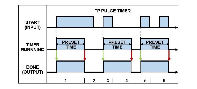
Below is the description of how a TP Pulse Timer operates in a PLC. The numbers correspond to the PLC Pulse Timer (TP) – timing diagram above…
- When the START input changes from FALSE to TRUE the PRESET TIME is loaded and the timer begins running. The DONE output is set to TRUE.
- If the timer expires while the START input is TRUE then the DONE output is reset to FALSE.
- When the START input changes from FALSE to TRUE the PRESET TIME is loaded and the timer begins running. The DONE output is set to TRUE.
- If the START input is reset to FALSE the timer keeps running. When the timer expires the DONE output is reset to FALSE.
- When the START input changes from FALSE to TRUE the PRESET TIME is loaded and the timer begins running. The DONE output is set to TRUE.
- If the START input transitions from TRUE to FALSE, while the timer is running, the timer is unaffected and keeps running. When the timer expires the DONE output is reset to FALSE.
How the Siemens SIMATIC Pulse Timer Works
The Siemens Simatic Pulse timer (S_PULSE) operates slightly differently compared to the TP pulse timer. You see, the Siemens Simatic Pulse timer resets the DONE output when the START input transitions from TRUE to FALSE. Whereas, the TP Pulse timer reset the DONE output after the preset time expires.
Check out the operation of a S_PULSE timer in a Siemens Simatic PLC using the timing diagram below…

Below is the description of how a S_PULSE Timer operates in a Siemens Simatic PLC. The numbers correspond to the PLC Pulse Timer – timing diagram above…
- When the START input changes from FALSE to TRUE the PRESET TIME is loaded and the timer begins running. The DONE output is set to TRUE.
- If the timer expires while the START input is TRUE then the DONE output is reset to FALSE.
- When the START input changes from FALSE to TRUE the PRESET TIME is loaded and the timer begins running. The DONE output is set to TRUE.
- If the START input is reset to FALSE then the DONE output is also reset to FALSE.
- When the START input changes from FALSE to TRUE the PRESET TIME is loaded and the timer begins running. The DONE output is set to TRUE.
- If the RESET input changes from FALSE to TRUE, the timer is stopped and the DONE output is reset to FALSE. After the RESET input has been triggered the timer can only be restarted if the RESET input is FALSE and the START input changes from FALSE to TRUE (Section 1).
6) PLC Extended Pulse Timer
The PLC Extended Pulse Timer operates in a very similar way to the Pulse Timer. However, as its name suggests, the Extended Pulse timer has an extended feature.
The Extended Pulse Timer (TE timer) creates an output PULSE with a pulse duration equal to that of the preset time value, just like the Pulse Timer. Additionally, the output pulse is EXTENDED if the input is re-triggered before the timer expires.
What is the difference between a Pulse Timer and Extended Pulse timer in a PLC? The PLC Pulse timer, once triggered, has a pulse duration equal to the preset time regardless of the input state. Whereas, the Extended Pulse timer restarts its timer every time the input is re-triggered, thus extending the pulse duration.
In my experience I’ve only come across Extended Pulse timers in Siemens PLCs and Unitronics PLCs. The Siemens SIMATIC PLC Extended Pulse timer instruction is known as a S_PEXT timer. While the Unitronics PLC Extended Pulse timer is known as a TE timer.
The Siemens SIMATIC PLC Extended Pulse timer (S_PEXT) and Unitronics PLC Extended Pulse timer (TE) instructions are shown below.…
How the Extended Pulse Timer Works
The Siemens PLC extended pulse timer uses the instruction name S_PEXT. While the Unitronics PLC extended pulse timer uses the instruction name TE. Even though these extended pulse timer have different instruction names their operation is essential the same.
A spectacular way to describe the operation of an Extended Pulse timer is by using a timing diagram like the one below…
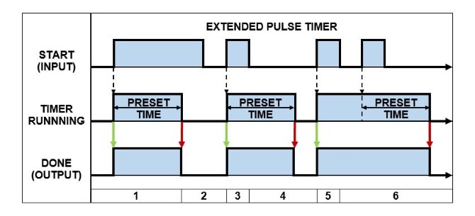
Below is the description of how an Extended Pulse Timer operates in a PLC. The numbers correspond to the PLC Extended Pulse Timer – timing diagram above…
- When the START input changes from FALSE to TRUE the PRESET TIME is loaded and the timer begins running. The DONE output is set to TRUE.
- If the timer expires while the START input is TRUE then the DONE output is reset to FALSE.
- When the START input changes from FALSE to TRUE the PRESET TIME is loaded and the timer begins running. The DONE output is set to TRUE.
- If the START input is reset to FALSE the timer keeps running. When the timer expires the DONE output is reset to FALSE.
- When the START input changes from FALSE to TRUE the PRESET TIME is loaded and the timer begins running. The DONE output is set to TRUE.
- If the START input transitions from TRUE to FALSE, while the timer is running, the timer is restarted. When the timer expires the DONE output is reset to FALSE.
7) PLC Frequency Timer
As far as I know, the Frequency timer is unique to the Automation Direct PLC. It works differently to other timers because it doesn’t introduce a time delay. In fact, I think it’s more like a frequency counter as opposed to a PLC timer.
In an Automation Direct PLC the Frequency timer is referred to as the FREQTMR instruction. The operation of the Frequency timer is a reflection of its name. Simply put, it measures the time between input pulses and converts it to a frequency value.
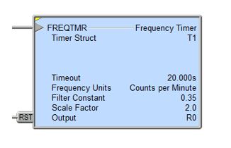
The frequency timer has a number of settings that enable it to be implemented to convert a pulsed input into the desired engineering units like speed or flow rate. These settings are:
- Frequency Time base in seconds, minutes or hours
- Filter for data smoothing
- Scaling factor
- Output as a REAL (floating point) variable
An example of a Frequency timer (FREQTMR) instruction used in an Automation Direct PLC is shown below.…
How the Frequency Timer Works
The function of a Frequency timer in an Automation Direct PLC is to monitor the occurrence of a certain event (input), measure the time between successive events and then convert the value to engineering units based on the time base, filter and scaling settings.
The Frequency timer output value can be reset in one of 2 ways:
- The reset input is set ON.
- The time between input pulses is longer than the Timeout setting.
An outstanding way to describe the operation of a Frequency timer in an Automation Direct PLC is by using a timing diagram like the one below…
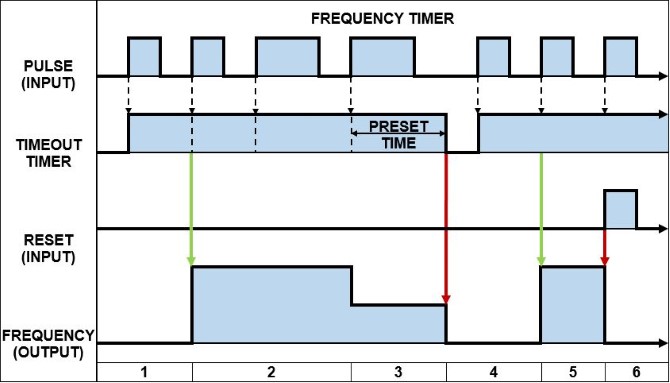
Below is the description of how a Frequency timer operates in an Automation Direct PLC. The numbers correspond to the Automation Direct PLC Frequency Timer (FREQTMR) – Timing Diagram above…
- When the PULSE input changes from FALSE to TRUE (positive edge signal) the TIMEOUT preset time is loaded and the TIMEOUT timer starts running.
- Initially, after two consecutive positive edge signals at the PULSE input the FREQUENCY output is calculated and its value set. The TIMEOUT preset time is reloaded each time there is a positive edge signal at the PULSE input.
- If the TIMEOUT timer expires before a positive edge signal at the PULSE input, the FREQUENCY output value is set to zero.
- When the PULSE input changes from FALSE to TRUE (positive edge signal) the TIMEOUT preset time is loaded and the TIMEOUT timer starts running.
- Initially, after two consecutive positive edge signals at the PULSE input the FREQUENCY output is calculated and its value set. The TIMEOUT preset time is reloaded each time there is a positive edge signal at the PULSE input.
- If the RESET input is set to TRUE the FREQUENCY output value is reset to zero.
8) PLC Teaching Timer
The Teaching timer is not a very common timer at all. In fact, I’ve only seen it in used in Mitsubishi PLCs and Idec PLCs. The Teaching timer doesn’t actually apply a time delay, but rather measures the time. Let’s check it out…
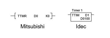
The Teaching timer is referred to as the TTMR instruction in the Mitsubishi PLC, while in the Idec PLC, the Teaching timer is referred to as the TTIM instruction. The Teaching timer works by monitoring the status of its input and storing the input ON duration time value in the allocated PLC data register.
A teaching timer is used to record the amount of time that the timers input is active for and store the recorded time in the PLC memory. The stored time value, recorded by the Teaching timer, can be scaled and used in other parts of the ladder logic program, like the preset time of a time instruction.
The difference between the Mitsubishi PLC and Idec PLC Teaching timers is one minor detail. The Mitsubishi PLC has an additional scaling factor that is applied as part of its teaching timer instruction. After the input ON duration has been measured the scaling factor is applied and then the result is stored.
The Mitsubishi PLC Teaching timer (TTMR) and Idec PLC Teaching timer (TTIM) instructions are shown below.…
How the Teaching Timer Works
The function of a Teaching timer in a PLC is to monitor the occurrence of an event (input), record the time that the input is ON and store the value in the PLC memory. The teaching timer is restarted when the input transitions from OFF to ON and the value is stored when the input transitions from ON to OFF.
A phenomenal way to describe the operation of a Teaching timer is by using a timing diagram like the one below….
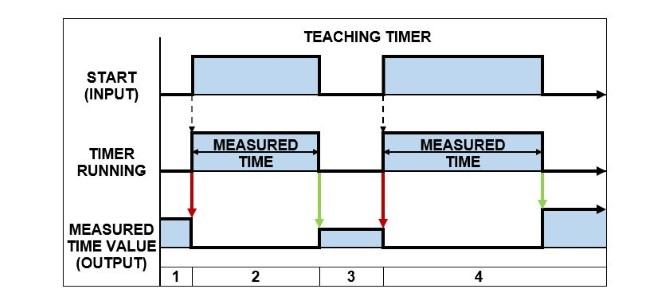
Below is the description of how a Teaching Timer operates in a PLC. The numbers correspond to the PLC Teaching Timer – timing diagram above…
- When the START input changes from FALSE to TRUE, the timer starts running and the last stored measured time value (output) is reset.
- When the START input changes from TRUE to FALSE the timer is stopped and the measured time value (output) is stored in the PLC memory.
- While the START input is FALSE, the measured time value (output) is retained in the PLC memory.
- Same as 1), 2) &3). Please note: the measured time value (output) increases in proportion to the time the start input is TRUE.
9) PLC Dual Timer
The Dual timer is another timer that is not commonly found in PLCs. In fact, I’ve only seen it used in Idec PLCs. The Dual timer has two timers built into the one instruction. These timers work together to create a pulsed output. Let’s take a closer look.…
The Dual timer is commonly referred to as the DTIM instruction in the Idec PLC. It has two built in timers which are used to generate a pulsed output whenever the status of its input is ON. The ON and OFF duration of the output pulse is set using the preset time inputs.
The Dual timer has a number of settings that enable it to be create a pulsed output. These settings are:
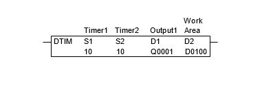
- S1 – Preset Time Input 1
- S2 – Preset Time Input 2
- D1 – Timer Done Output
- D2 – System Work Area (2x Data Registers)
As with other Idec PLC timers, there are multiple instruction names for the Dual timer depending on the time base value. So if the preset time value is 10 and the time base is 100ms, then the actual timer value is 10 x 100ms = 1000ms, or 1sec. Here are the Dual timer instructions and their respective time base values….
- DTML = 1 s time base
- DTIM = 100 ms time base
- DTMH = 10 ms time base
- DTMS = 1 ms time base
An example of an Idec PLC Dual timer (DTIM timer) instruction is shown below. It has a time base of 100ms with both S1 and S2 preset time values equal to 10. So it has a 1 second ON and 1 second OFF pulse output.…
How the Dual Timer Works
The function of a Dual timer in an Idec PLC is to monitor the status of the timer input and generate a pulsed output according to the preset time values. The output pulse generated by the Dual timer is active as long as the status of the timer input is ON.
A splendid way to describe the operation of a Dual timer in an Idec PLC is by using a timing diagram like the one below….
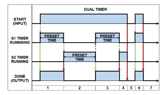
Below is the description of how a Dual Timer operates in a PLC. The numbers correspond to the IDEC Dual Timer – timing diagram above….
- When the START input changes from FALSE to TRUE the S1 PRESET TIME is loaded and the S1 timer begins running. The DONE output is set to TRUE.
- After the S1 timer expires, the DONE output is reset to FALSE. The S2 PRESET TIME is loaded and the S2 timer begins running.
- After the S2 timer expires, the DONE output is set to TRUE. The S1 PRESET TIME is loaded and the S1 timer begins running.
- After the S1 timer expires, the DONE output is reset to FALSE. The S2 PRESET TIME is loaded and the S2 timer begins running.
- If the START input transitions from TRUE to FALSE, while the timers are running, the timers are stopped and the DONE output is reset to FALSE.
- When the START input changes from FALSE to TRUE the S1 PRESET TIME is loaded and the S1 timer begins running. The DONE output is set to TRUE.
- If the START input transitions from TRUE to FALSE, while the timers are running, the timers are stopped and the DONE output is reset to FALSE.
The Dual timer in an Idec PLC creates a pulsed output with a single instruction. However, in other PLCs a timed pulsing output must be created with ladder logic using 2x ON delay timer instruction. The functionality of 2 timers is built into the Dual timer instruction.
10) PLC Multi Output Timer
The Multi Output timer is yet another not-so-common timer. It uses a single timer, with multiple preset time values and multiple outputs. This “beast of a timer” is only found in some Omron PLCs.
In an Omron PLC the Multi Output timer is referred to as the MTIM instruction. It has eight independent done outputs each with their own preset time input. The Multi Output timer works just like an ON Delay timer (TON Timer). Each output is delayed from turning on by its corresponding preset time value.
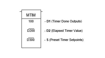
Multi Output timer has a number of settings that enable it produce multiple done outputs. These settings are:
- D1 – Timer Done Outputs.
- D2 – Elapsed Time Output.
- S – Preset Time Inputs.
D1 contains the 8 Timer Done Output bits. It uses bit 0-7 for the Timer Done Outputs, bit 8 for Reset and bit 9 for Pause. Bits 10-15 are not used.
- D1 – Bit0: Timer Done Output 1.
- D1 – Bit1: Timer Done Output 2.
- D1 – Bit2: Timer Done Output 3.
- D1 – Bit3: Timer Done Output 4.
- D1 – Bit4: Timer Done Output 5.
- D1 – Bit5: Timer Done Output 6.
- D1 – Bit6: Timer Done Output 7.
- D1 – Bit7: Timer Done Output 8.
- D1 – Bit8: Reset Input.
- D1 – Bit9: Pause Input.
D2 contains the elapsed timer value.
S1 is assigned to the Preset Time Input 1, which acts as an address pointer. An address offset is used to allocate a separate Preset Time Input for each timer output. See below:
- S1+0: Preset Time Input 1.
- S1+1: Preset Time Input 2.
- S1+2: Preset Time Input 3.
- S1+3: Preset Time Input 4.
- S1+4: Preset Time Input 5.
- S1+5: Preset Time Input 6.
- S1+6: Preset Time Input 7.
- S1+7: Preset Time Input 8.
An example of an Omron PLC Multi Output timer (MTIM) instruction is shown below….
How the Multi Output Timer Works
The function of a Multi Output timer in an Omron PLC is to monitor the status of the timer input and generates eight done output bits according to the preset time values. All eight timer done outputs are generated independently and are based their own separate preset time values.
The MTIM instruction has a time base of 100ms with a max preset time value of 999.9 seconds. If a preset time value is set to 0 then all subsequent preset time values are ignored. The reset bit sets the elapsed timer value back to zero and the timer done output bits to FALSE.
An amazing way to describe the operation of a Multi Output timer in an Omron PLC is by using a timing diagram like the one below….
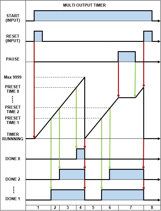
Below is the description of how a Multi Output Timer operates in an Omron PLC. The numbers correspond to the Omron PLC Multi Output Timer – timing diagram above…
- When the START input changes from FALSE to TRUE and the RESET input is triggered all the DONE output bits are reset to FALSE and the timer is restarted.
- The timer counts up and when PRESET TIME 1 value is reached the DONE 1 output is set TRUE.
- The timer continues to count up and when PRESET TIME 2 value is reached the DONE 2 output is set TRUE.
- The timer continues to count up and as each PRESET TIME value is reached the corresponding DONE output is set true up to PRESTE TIME 8 where DONE 8 output is set TRUE.
- Once the timer reaches the max value of 9999 the timer restarts and all DONE outputs are reset to FALSE.
- The timer continues to count up and when PRESET TIME 1 & 2 values are reached the corresponding DONE outputs are set TRUE.
- When the PAUSE input changes from FALSE to TRUE the timer stops counting up and the DONE outputs do not change state. After the PAUSE input resets back to FALSE the timer continues to count up.
- If the RESET input is triggered and the START input is reset to FALSE, all the DONE outputs are also reset to FALSE and the timer is reset and stopped
11) PLC Special Timer
I’ve saved “the best” PLC timer instruction for last. It’s called the Special timer. It certainly is “special”. I’ve only ever seen the Special timer used in Mitsubishi and Delta PLCs. This sucker has four separate timer functions built into the one PLC instruction. What a monster! Let’s take a closer look.…
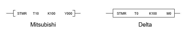
The Special timer is commonly referred to as the STMR instruction in the Mitsubishi and Delta PLCs. The Special timer uses only one timer and one PRESET TIME input. But has four separate timer instructions built into it, each with their own DONE output.
The four types of timer functions contained in the Special timer are the OFF delay timer, Pulse timer (OFF), Pulse timer (ON) and a combined ON delay + OFF delay timer.
The four timer functions of the Special timer are assigned to the DONE output (D) which acts as an address pointer. An address offset is used to allocate a separate DONE output bits for each timer output. See below….
- D+0: OFF delay timer.
- D+1: Pulse timer (OFF).
- D+2: Pulse timer (ON).
- D+3: Combined ON delay timer + OFF delay timer.
Examples of the Mitsubishi PLC and Delta PLC Special timer (STMR timer) instructions are shown below….
How the Special Timer Works
The function of a Special timer in the Mitsubishi and Delta PLCs is to monitor the status of the timer input and generate the four types of timer done outputs according to the preset time values. All four timer done outputs are based on a single preset time value and are generated separately.
An awe-inspiring way to describe the operation of a Special timer in a Mitsubishi and Delta PLC is by using a timing diagram like the one below….
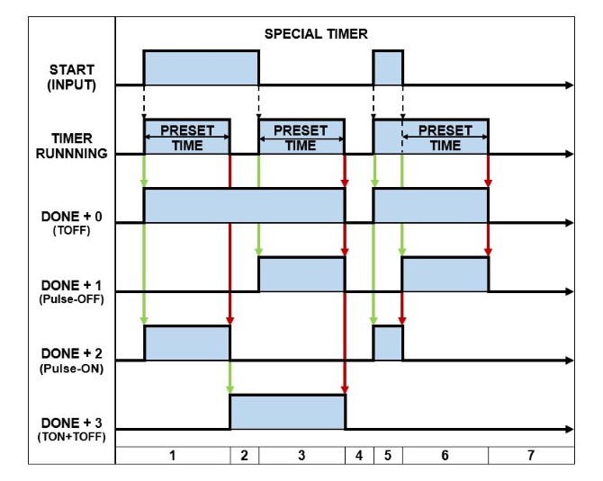
Below is the description of how a Special Timer operates in a PLC. The numbers correspond to the Mitsubishi & Delta PLC Special Timer – timing diagram above…
- When the START input changes from FALSE to TRUE the PRESET TIME is loaded, the timer begins running and :
- D+0 output (TOFF) is set to TRUE.
- D+1 output (Pulse-OFF) is reset to FALSE.
- D+2 output (Pulse-ON) is set to TRUE.
- D+3 output (TON+TOFF) is reset to FALSE.
- If the timer expires, while the START input is TRUE, then :
- D+0 output (TOFF) remains TRUE.
- D+1 output (Pulse-OFF) remains FALSE.
- D+2 output (Pulse-ON) is reset to FALSE.
- D+3 output (TON+TOFF) is set to TRUE.
- After the preset time has expired and the START input is reset to FALSE, the PRESET TIME is loaded, the timer begins running and :
- D+0 output (TOFF) remains TRUE.
- D+1 output (Pulse-OFF) is set to TRUE.
- D+2 output (Pulse-ON) remains FALSE.
- D+3 output (TON+TOFF) is remains TRUE.
- If the timer expires, while the START input is FALSE, then :
- D+0 output (TOFF) is reset to FALSE.
- D+1 output (Pulse-OFF) is reset to FALSE.
- D+2 output (Pulse-ON) remains FALSE.
- D+3 output (TON+TOFF) is reset to FALSE.
- When the START input changes from FALSE to TRUE the PRESET TIME is loaded and the timer begins running :
- D+0 output (TOFF) is set to TRUE.
- D+1 output (Pulse-OFF) is reset to FALSE.
- D+2 output (Pulse-ON) is set TRUE.
- D+3 output (TON+TOFF) is reset to FALSE.
- If the START input changes from TRUE back to FALSE, before the timer gets a chance to expire, then the PRESET TIME is loaded and the timer restarts :
- D+0 output (TOFF) remains TRUE.
- D+1 output (Pulse-OFF) is set to TRUE.
- D+2 output (Pulse-ON) is reset to FALSE.
- D+3 output (TON+TOFF) remains FALSE.
- If the START input remains FALSE and the timer expires, then :
- D+0 output (TOFF) is reset to FALSE.
- D+1 output (Pulse-OFF) is reset to FALSE.
- D+2 output (Pulse-ON) remains FALSE.
- D+3 output (TON+TOFF) remains FALSE.
WOW, that’s a lot of PLC timers to swallow in one hit. If you’ve made it this far, give yourself a rather long “pat on the back”…. WELL DONE TO YOU!
What I’ve found, when using timers while ladder logic programming a PLC, is that I mainly use TON (Delay ON) and TOFF (Delay OFF) timers. Occasionally I will have the need to use some of the other types of timers.
In the next section there are some juicy must have PLC timer examples. Click here to go to the next section.