PLC toggle logic emulates the function of flip flop circuits that are commonly used in electronics and computer systems.
What is a Flip Flop in a PLC?
You may have heard of a flip flop in electronics and computer systems, but what is a flip flop in a PLC?
A flip flop in PLC programming is created using toggle logic. Whenever the state of the PLC input changes momentarily, the state of the PLC output will be latched to the opposite of it’s current state. There can be either 1 or 2 inputs and outputs depending on the type of PLC flip flop function required.
Understanding the flip flip function is the key to developing PLC toggle logic. So let’s take a closer look at the different types of flip flops used in a PLC, how they work, how to program them and what they can be used for.
The 3 Most Useful Types of Flip Flops in a PLC
There are several types of flip flops used in electronics and computer systems, but which types are the most useful in a PLC?
The 3 most useful types of flip flops that can be emulated using PLC toggle logic are:
- T Flip Flop
- SR Flip Flop
- JK Flip Flop
The type of flip flop that is chosen will mainly depend on how many inputs are required to trigger the output to toggle it’s state. If one input is required then then T flip flop type is suited. But if 2 inputs are required then the SR flip flop or JK flip flop types are required.
Let’s look at how the electronic flip flops translate into PLC flip flops:
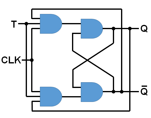
The T flip flop has a T input, a CLOCK input, a Q output and a NOT Q output. This type of flip flop toggles the state of the output whenever the state of the input is TRUE and the CLOCK input is triggered.
When the T flip flop is implemented using PLC toggle logic we use one input and generally only one output. There is no need for a CLOCK input and a second output can be added if a NOT output is required.
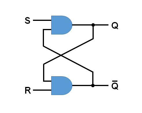
The SR flip flop has a S input, a R input, a Q output and a NOT Q output. This type of flip flop toggles the output depending on the state of the S and R inputs.
When the SR flip flop is implemented using PLC toggle logic we use two inputs and one output. The two inputs are called Set and Reset. A second output can be added if a NOT output is required.
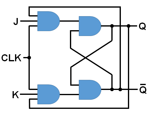
The JK flip flop has the same inputs and outputs as a SR flip flop except it has an extra CLOCK input.
The JK flip flop operates the same way as a SR flip flop except it has bit stable operation when both inputs are in the same state. The CLOCK input in the JK flip flop facilitates bit stable operation by only initiating an output toggle when the CLOCK input is triggered.
When we talk about JK and SR flip flops in a PLC we refer to both of them as ladder logic SR flip flops. The differentiation in functionality isn’t made because bit stable operation can be achieved for the SR flip flop in a PLC without the need for the third clock input.
In fact, by virtue of our ladder logic code and the nature of the PLC scan cycle, we can choose the state of the PLC output when both PLC inputs are the same state. In this scenario, if we require that the output state be FALSE then we use SR flip flop toggle logic. However, if we require that the output state be TRUE then we use a RS flip flop toggle logic.
How Does a PLC Flip Flop Work?
A handy piece of ladder logic programming to have in your kit is the flip flop, but do you know how it works in a PLC?
The operation of a flip flop function in a PLC utilizes both PLC inputs and PLC outputs. The PLC output is fed back to the input logic so that the state of the flip flop output is dependent on both the state of the input and the current state of the output.
So when the input is triggered and the state of the output is FALSE then the output will toggle from FALSE to TRUE. And vice versa, when the input is triggered and the state of the output is TRUE then the output will toggle from TRUE to FALSE. Hence the use of the term flip flop.
Let’s look at the most common types of flip flops and how they work in a PLC in a little more detail….
How Ladder Logic T Flip Flop Works in a PLC
The ladder logic T flip flop is probably the mostly used flip flop when it comes to PLC programming.
When used in a PLC the ladder logic T flip flop has 1 input that is used to toggle the flip flop output every time the input changes state from FALSE to TRUE.
The operation of a ladder logic T flip flop is summarized in the truth table below:
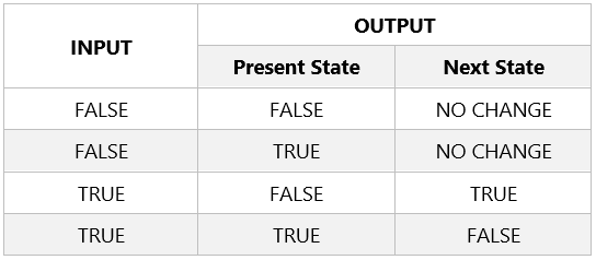
When the state of the PLC output is TRUE and the state of the PLC input changes from FALSE to TRUE, the state of the PLC output will change to FALSE and be maintained. Even if the state of the PLC input changes back to FALSE.
When the state of the PLC output is FALSE and the state of the PLC input changes from FALSE to TRUE, the state of the PLC output will change to TRUE and be maintained. Even if the state of the PLC input changes back to FALSE.
When the PLC input is FALSE, there is no change to the state of the PLC output and it maintained at it’s present state.
How Ladder Logic RS and SR Flip Flop Works in a PLC
The RS and SR flip flops operate a little differently to the T flip flop. So how exactly do the RS and SR flip flops work in a PLC?
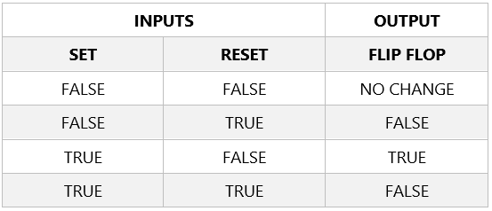
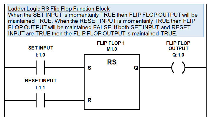
The ladder logic RS and SR flip flop in a PLC have SET and RESET inputs that are used to toggle the state of the flip flop output. When the SET input is TRUE, the state of the flip flop output is maintained TRUE, even if the SET input changes state back to FALSE. The state of the flip flop output will only revert back to FALSE if the RESET input is TRUE.
If both the SET and RESET inputs are FALSE then there is no change in the state of the flip flop output.
The difference in the operation of a ladder logic RS and SR flip flop is the way they handle the situation where both SET and RESET inputs are TRUE at the same time. When both SET and RESET inputs are TRUE at the same time the ladder logic SR flip flop unlatches the output to FALSE. Whereas, the ladder logic RS flip flop latches the output to TRUE.
The operation of a ladder logic SR flip flop is summarized in the truth table below:
The operation of a ladder logic RS flip flop is summarized in the truth table below:

How to Program a Toggle Logic in a PLC Using Ladder Logic
Now that we know the most useful types of flip flops and understand their operation, let’s see how to program them in a PLC using ladder logic.
The main PLC programming component for developing toggle logic is a PLC output latch. Equally important is PLC output feedback logic so that the state of the flip flop output is dependent on both the state of the input and the current state of the output. The most popular way to program toggle logic for a flip flop in a PLC is by using ladder logic.
The three main methods of programming PLC toggle logic using ladder logic are latching logic, SET and RESET instructions and flip flop function blocks.
In order for an electronic T flip flop to have bit stable operation we need to use a clock input. However, with a ladder logic flip flop the PLC scan acts as a kind of clocked input providing a cyclic update of the program state. We can use this to our advantage in our ladder diagram to program in bit stable operation.
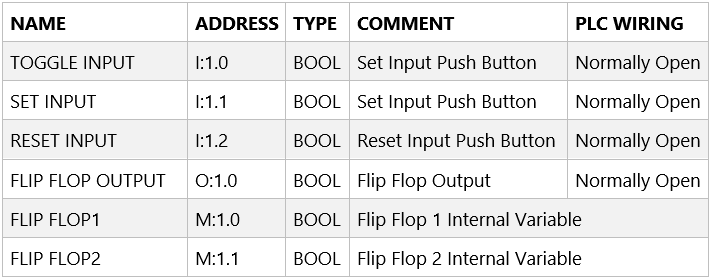
To implement a ladder logic flip flop in a PLC let’s firstly list the required inputs, outputs and internal variables.
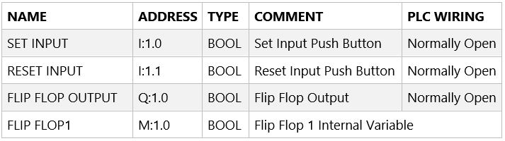
PLC manufacturers use different memory address allocation so the input, output and internal variable allocations used here are arbitrary address. Below is the list of required inputs, outputs and internal variables that need to be declared:
T Flip Flop Ladder Logic Examples
The 3 most common ways to program toggle logic for a T Flip flop in any PLC using ladder logic are:
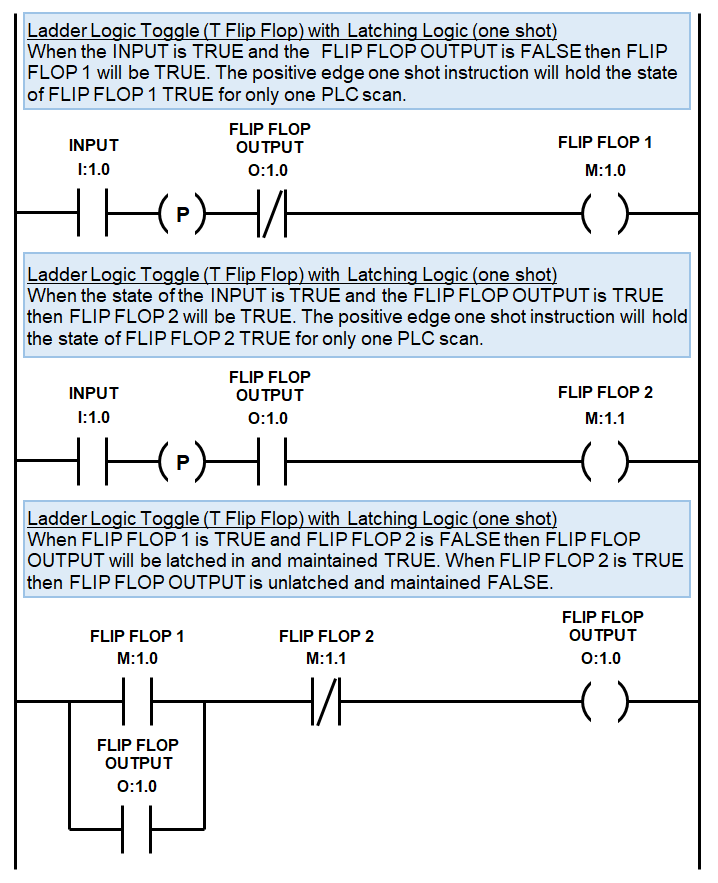
- Positive edge one shot instructions and latching logic.
- Latching logic.
- SET and RESET instructions.
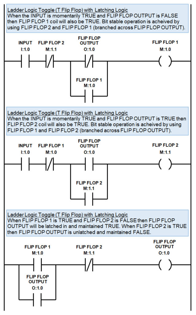
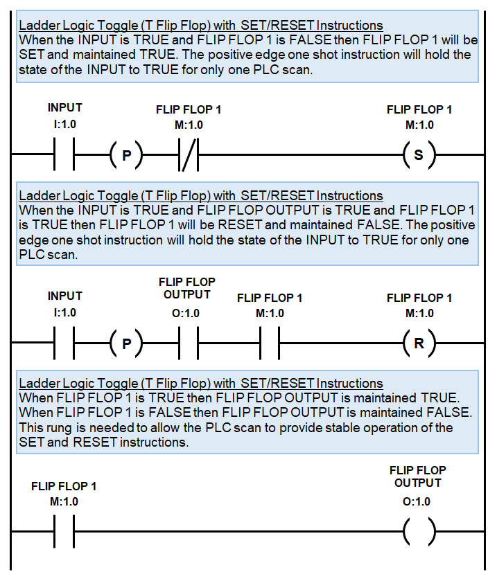
The 1st T flip flop ladder diagram example uses positive edge one shot instructions and latching logic:
The 2nd T flip flop ladder diagram example uses latching logic. But, if you’re working with a super basic mega cheap PLC it may not have one shot instructions and you may be forced to use this method.….
The 3rd T flip flop ladder diagram example uses SET and RESET instructions, which tends to simplify the ladder diagram a little….
SR Flip Flop Ladder Logic Examples
The 2 most common ways to program toggle logic for a SR Flip flop in any PLC using ladder logic are:
- Latching logic.
- SET and RESET instructions.
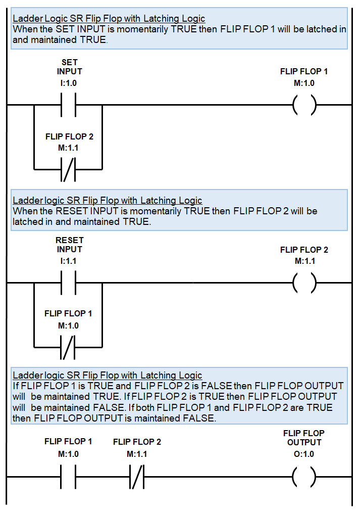
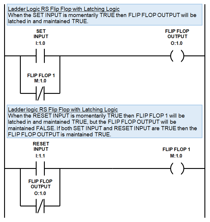
The 1st SR Flip Flop ladder diagram example using latching logic is shown below….
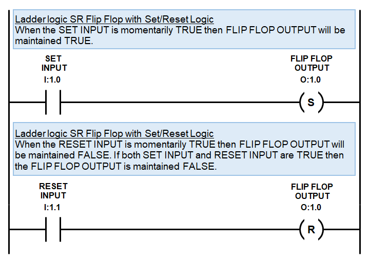
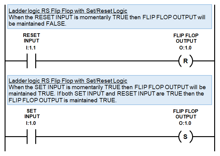
The 2nd SR Flip Flop ladder diagram example using SET and RESET instructions is shown below….
RS Flip Flop Ladder Logic Examples
Remember, compared to the ladder logic SR flip flop, the ladder logic RS flip flop is the same except it has a different result when both SET and RESET inputs are TRUE. We can achieve this by using the PLC scan to our advantage and rearranging the code a little.
The 2 most common ways to program toggle logic for a RS Flip flop in any PLC using ladder logic are:
- Latching logic.
- SET and RESET instructions.
The 1st RS Flip Flop ladder diagram example using latching logic is shown below….
The 2nd RS Flip Flop ladder diagram example using SET and RESET instructions is shown below….
Ladder Logic RS and SR Flip Flop in a Siemens PLC
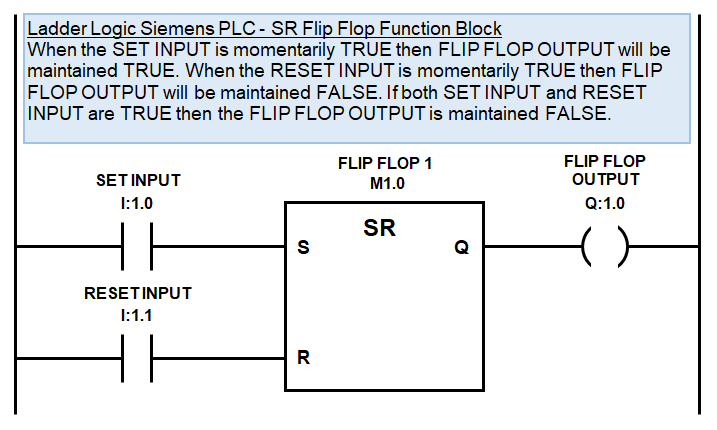
The Siemens PLC has dedicated ladder logic RS and SR flip flop function blocks as part of their standard instruction library.
These function blocks operate exactly the same way as the other ladder logic RS and SR flip flop examples, but requires an internal variable to be assigned to the function block.
The memory address allocation for a Siemens PLC is I=Inputs, Q=outputs and M=Internal Variables. Below is the list of required inputs, outputs and internal variables that need to be declared for a Siemens PLC…..
Siemens PLC SR Flip Flop Ladder Logic Example
The Siemens PLC SR flip flop function block has been implemented in the ladder diagram example below…
Siemens PLC RS Flip Flop Ladder Logic Examples
The Siemens PLC RS flip flop function block is programmed in a similar fashion to the SR flip flop function bock as per the ladder diagram example below…
How Can a Flip Flop Be Used in a PLC?
Now that you’re full bottle on PLC flip flops and PLC toggle logic you might be wondering how they can be used in a PLC ladder logic program?
Using a ladder logic flip flop in a PLC is simple. If there is a situation where 1 input must toggle an output, then use a ladder logic T flip flop. If there is a situation where 2 inputs are required to toggle an output then use a ladder logic RS or SR flip flop.

A Ladder logic flip flop application example could be a silo fill control sequence.
We could utilize north and south selection push button inputs and implement a ladder logic SR flip flop to control which silo gets filled. Also, a pause toggle switch input could be implemented using a ladder logic T flip flop in order to pause and resume the sequence to allow for foreign debris to be removed from the inspection conveyor.
So when the operator pushes the north or south selection buttons the silo feed diverter changes position from north to south and vice versa.
And when the operator pushes the pause toggle switch the filling sequence stops, the foreign debris is removed, then the pause toggle switch is pressed again and the sequence resumes from where it left off.
Now that you know enough to be dangerous it’s time to get your hands dirty on a PLC Programming Simulator.
To go to the next section click here.