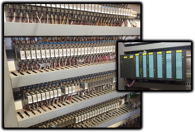
Relay logic is a hard wired control system using instrumentation, switches, timers, relays, contactors, motors and actuators. Traditional machine and process automation was accomplished using relay logic. Automating a machine using relay logic requires a mass of wiring and magnitude of devices to perform even the simplest of tasks.
Some of the other problems with implementing relay logic are:
- Requires a lot of switchboard space.
- Installation is very labor intensive.
- Trouble shooting is extremely difficult.
- Modifications to the control functionality are complicated and seriously tedious.

The advent of the microprocessor meant that relay logic control functionality could be programmed and stored in a computer. In the late 1960’s some really brainy people realized this and pressed ahead to create a device called a Programmable Logic Controller (PLC).
Relay logic in a PLC is the method of formulating logical expressions in order to automate machinery and processes in industrial applications. The programming language that is used to create relay logic in a PLC is called Ladder Logic.
This was a massive breakthrough in the industrial automation industry which would eventually render relay logic control systems near redundant.
In an automated control system the main advantages of a PLC over relays are:
- Easier to develop complex logical expressions with ladder logic software.
- Increased reliability with PLC life easily reaching +10years,
- Easier and cheaper to modify or expand the control system at a later date.
- Reduced design, installation and component costs.
- Virtually maintenance free compared to relays.
- Superior monitoring and reporting functionality making process trouble shooting and optimization easier.

To understand the difference between relay logic and ladder logic it’s really important that you understand relay logic and how a relay works. Understanding relay logic is a good stepping stone to understanding ladder logic. After all, ladder logic was originally derived from relay logic. Makes sense, right?
How Do Relay Logic Systems Work?
Relay logic systems are a network of hard wired electrical components. The relay is the fundamental component and it works by switching electric circuits on and off to form logic operations that in turn provide process control to the system. You can think of relay logic systems as a mechanical computer that does computation with 1’s and 0’s by switching relays instead of using a silicon chip.
The fundamental component of a relay logic is the relay. So let’s look at how relays work in a little more detail…
What Is A Relay?
A relay is an electromechanical device that consists of two basic components, a relay coil and relay contact. The relay contact is used to switch a circuit on or off and the relay coil is used to change the state of the relay contact. The three main types of relays are spring return relays, latching relays and multipole relays.
Why Are Relays Used In Control Circuits?
Relays are used because they allow electric isolation between the switching circuit (contact) and control signal circuit (coil) via means of electromagnetics. That means relays can be used to connect circuits with different voltage and current levels to control equipment like motors and actuators. A relay can also switch multiple circuits with different states at the same time making them ideal for logic control circuits in industrial automation.
What Functions Does A Relay Perform?
Relays perform 3 main functions in an electric circuit:
- Allowing control circuits to switch a load circuit even if the voltages of both circuit are different.
- Able to switch a high current device using a low current electronic control signal.
- Relays can be wired in combination to perform logical operations using a network of electric circuits known as relay logic.
How a Relay Works
A relay is an electromechanical device that consists of two basic components….
- Relay coil.
- Relay Contact.
A relay coil is essentially copper wire wound around a chunk of iron that is used to produce an electromagnetic field that can attract metal. Think of a junk yard crane that is used to pick up scrap metal. It uses the same principle to generate a magnetic field that attracts metal.
A relay contact is basically a switch that is used to turn an electric circuit on or off.
Hang on a minute! If the contacts of a relay turn an electric circuit on or off why do we need the coil?
Well, the relay coil’s purpose is to change the state of the relay contacts. Just like your finger is used to change the state of a light switch from off to on. So, we are changing the state of the contacts using an electrical signal instead of your using your finger.

To energize the coil we need to connect it to a voltage source, which is sometimes called a relay input.
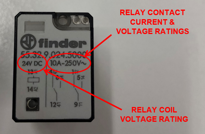
Some common DC voltage relays are 5V relay, 12V relay and 24V relay. Some common AC voltage relays are 120VAC relay and 240VAC relay.
The voltage rating is usually written on the casing of the relay. The coil voltage rating needs to be adhered to otherwise the relay coil may fail to change the state of the contacts or overheat and burn out.
When we energize the relay coil with it’s rated voltage it allows current to flow within the relay coil and produces and electromagnetic field. This electromagnetic field is used to attract the relay contact towards the relay coil, thus changing the state of the relay contacts.
The relay contacts are either configured normally open (NO) or normally closed (NC). Quite often a relay will have changeover contacts.
So what is a changeover contact?
A changeover contact is the combination of both normally open (NO) and normally closed (NC) contacts in the same contact block. The changeover contact allows selection of either the normally open (NO) or the normally closed (NC) contact depending on the way it is wired. It is sometimes called a double throw contact.
The contact voltage and current rating is usually written on the casing of the relay. The contact voltage and current rating needs to be adhered to otherwise the relay contact may overheat and burn out.
If the relay coil voltage rating and contact voltage and current rating are not written on the relay casing then check the relay base. Sometimes it’s a combination of both the case and base. If all else fails then consult the data sheet.
Relay Operation
If a relay is wired to a normally open (NO) contact and the relay is energized then the contact will change state from OPEN to CLOSED…..
 Contact")
If a relay is wired to a normally closed (NC) contact and the relay is energized then the contact will change state from CLOSED to OPEN…..
 Contact")
If a relay with changeover contacts is wired in a normally open (NO) configuration and the relay is energized then the contact will change state from OPEN to CLOSED…..
")
If a relay with changeover contacts is wired in a normally closed (NC) configuration and the relay is energized then the contact will change state from CLOSED to OPEN. Notice that the wiring of the contacts has changed sides…..
")
Types of Relays
There are several types of relays each with their specific characteristics and uses. The 3 types that are used frequently in industrial applications are spring return relays, latching relays and multipole relays.
Spring Return Relay
The most common relays are spring return relays. They have one relay coil and use a spring to return the relay contact back to it’s normal state after the relay coil is de-energized and the electromagnetic field has collapses.
The relay coil must be energized at all times in order for the state of the relay contact to remain in it’s changed state. As soon as the coil is de-energized then the relay contact returns back to it’s normal state.
Can you see the spring in the “Electromechanical Relay” picture above? The spring is at the very top of the relay.
Latching Relay
A latching relay is a type of relay that can change and maintain the state of the contact without the need for the coil to be constantly energized. It utilizes two separate coils, each of which are responsible for a certain state of the contact either open or closed. A short voltage pulse to energize either coil in the latching relay is all that is required to change the state of the contact.
Multi Pole Relay
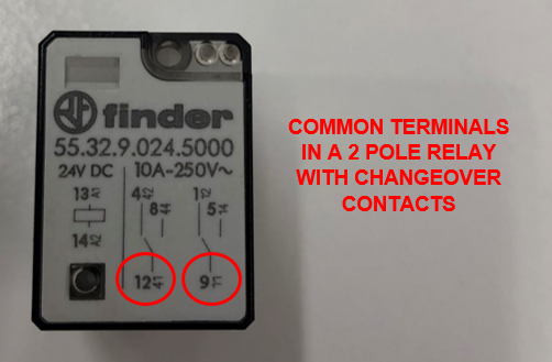
A multi pole relay is any type of relay with more than one contact. Each relay contact is called a pole. So a relay with two contacts will be called a two pole relay and a relay with four contacts will be called a four pole relay.
When using multi pole relays multiple coils are not required to change the state of the contacts. The state of all the relay contacts is changed at the same time by a single relay coil.

In short, the operation of a single pole relay is the same as a multi pole relay, we just have more contacts to play with!
This is handy when we are activating more than one device. Especially when the devices need different voltage levels or the combined current draw of multiple devices exceeds the current rating of a single contact. It’s also handy having multi pole relays when the process control logic gets complex.
How do you connect a Relay?
In order to connect a relay we need to wire the coil to a voltage supply (generally switched) and the contacts to the load device like a light, motor, solenoid valve or another relay. This can be done by connecting the relay coil and contact wires to the terminals of a relay base. The relay base terminal allocation for connection is usually drawn on the relay casing, labelled on the relay base or detailed in the relay data sheet.

The common on a relay is the terminal associated with the part of the contact that does not switch when the relay coil is energized. In a relay with a changeover contact it is the terminal “common” to both the NO and NC contacts. When the common is wired correctly it is connected to the load supply voltage.
Relay Logic Circuits
The fundamental elements of relay logic circuits are….
- Power supply.
- Relay components.
- Connection wires.
The power supply voltage needs to match the rated relay coil voltage. Also, the power supply needs to be big enough to accommodate the current draw of all the relays when they are energized.
The relays are selected according to the power supply’s output voltage, functionality and current rating of the contacts required.
Because relay logic is a hard wired system some sort of wiring diagram or relay schematic diagram is required to make sense of it all.
Now please take note, there are many ways to draw an electric circuit. Depending on which country you are from will determine which standard relay wiring diagram you will need to use. The way circuits are laid out and the component symbols will vary from one drawing standard to the next. Also, some drawing standards arrange their control circuits from left to right and some use top to bottom. Check out the sample drawings below….

For the purposes of this explanation a left to right arrangement will be used because it ties in with ladder logic diagrams later on.
A relay schematic diagram consists of a supply voltage rail on the left hand side and a zero voltage rail on the right hand side drawn as vertical lines.
The relay components and other devices are packed in between connected by wires, drawn as horizontal lines, to form a circuit.
Relay Logic Symbols
The relay coil and relay contacts can be drawn as per the relay logic symbols diagram below….

How to Read a Relay Schematic
The most basic of relay logic circuits uses a power supply, a relay, a switch and a device that needs to be switched ON or OFF all wired together as shown in the simple relay diagram below….

The above relay logic circuit example shows a lamp (Lamp No.1) being switched on via a relay (Relay No.1).
The first line has a rotary switch connected to the coil of Relay No.1 with the relay coil labelled as R1.
The second line has a normally open contact from Relay No.1 also labelled R1 which is connected to Lamp No.1.
To aid in understanding relay schematics the sequence of events is read from the first horizontal line downwards and from the left hand side power rail to the right hand side power rail.
We read from left to right because the potential difference between the left and right hand side power rails creates current flow in that direction. In the example relay schematics a green line is used to highlight current flow in the circuit.
So, in the first line we start at the left hand side power rail and follow the horizontal line until we get to the normally open Rotary Switch.
If the rotary switch is in the OPEN state there is an open circuit and current cannot flow to the right hand side of the circuit. So the relay coil (R1) stays de-energized.
If we go to the second line we notice that the normally open relay contact (R1) stays OPEN because Relay No.1 coil (R1) is de-energized. Therefore there is also an open circuit on the second line so no current can flow to the lamp and it stays OFF….

What happens when we turn the Rotary Switch on?
When the Rotary Switch is turned ON it’s state changes from OPEN to CLOSED.
If we look at the first line and start at the left hand side power rail then follow the horizontal line until we get to the Rotary Switch we can observe that it is in the CLOSED state and current can flow to the right hand side of the circuit.
So in this case the relay coil (R1) is energized and then we reach the end of the right hand side rail.
Now let’s go to the left hand side of the second line where we notice that the normally open relay contact (R1) has also changed state to CLOSED because the relay coil is energized.
Therefore there is a closed circuit on the second line so current can flow to the right hand side of the circuit and Lamp No1 turns ON….

Let’s spice it up and add another line to the relay logic circuit.
This time we’ll use a second relay contact from Relay No1 and wire it as a normally closed contact. Then we’ll add a second lamp (Lamp No2) to the new circuit.
In this case the operation of that lamp will be reversed. So when the Rotary Switch is OFF, Lamp No.2 is ON and when the Rotary Switch is ON, Lamp No.2 is OFF.
Wait, what????
Don’t believe me then check out the relay logic circuit below….

The new relay contact in the third line is now a normally closed instead of normally open.
When Relay No.1 coil is de-energized it’s normally closed contact is in it’s normal state, that is CLOSED.
When Relay No.1 coil is energized it’s normally closed contact changes state to OPEN.
A normally closed contact behaves the opposite of a normally open contact. It’s sometimes referred to as reverse relay logic or just reverse logic. See below….

Ladder Logic Control
Remember the statement earlier on this page – Ladder Logic was originally derived from Relay Logic.
So, what is the difference between relay logic and ladder logic?
The big difference between relay logic and ladder logic is that relay logic needs to hard wire each and every control circuit for every single control function. Whereas ladder logic uses the assistance of a microprocessor based device called a Programmable Logic Controller (PLC).
And, how does a PLC differ from relay logic?
The difference between a PLC and relay logic is that a PLC is a programmable device whereas relay logic is a network of hardwired electrical devices. Both a PLC and relay logic can perform logical computation, but a PLC does it using a microprocessor and relay logic does it using electric circuits.
So essentially what we are doing is getting a mass of relays and wires and replacing them with a tiny box that has awesome computing power.
Even with a PLC and ladder logic programming we still need to hard wire certain devices such as the switches and lamps just like in the relay logic examples above. But the wiring is greatly reduced because only the input and output devices need hard wiring. The control relays that are used to form the control functionality and logic functions are replaced by the ladder logic program stored internally within the PLC memory.

The format of a ladder logic diagram is similar to that of a relay logic circuit.
There is power rail on the left hand side and a power rail on the right hand side drawn as vertical lines.
The logic programming is inserted in between the power rails and connected with horizontal lines to form a logic expression.
Each line of the ladder logic diagram is called a rung.
STOP…. rails and rungs….That’s why the term “Ladder” is used in Ladder Logic…. Light bulb moment!
However the symbols used are a bit different to the relay logic circuit drawings. Check out the table below to compare the differences of the basic components…

If we were to use a latching relay which uses two coils, one to latch (or set) the relay and the other to un-latch (or reset) the relay. The relay symbols are represented as below….

To outline the difference let’s use the example above where a switch is turning two lamps ON and OFF alternatively.
If we use a PLC with a ladder logic program we firstly need to hard wire the switch to the input terminals of the PLC. Then we need to hard wire the lamps to the output terminals. Lastly, we need to write our ladder logic program and load it into the PLC memory.
The diagram below shows a ladder logic diagram when the Rotary Switch is OFF….

The diagram below shows a ladder logic diagram when the Rotary Switch is on.
Remember the normally closed contact is reverse logic!

Ladder Logic Advantages
Some of the advantages that ladder logic control systems have over relay logic control systems are:
- Installation time is greatly reduced with ladder logic control systems due to the reduced amount of hard wiring required. In other words, we only need to hard wire the input and output devices. The control logic is implemented using software not hard wired relays.
- Modifications to the control logic can easily be done using software to modify the ladder logic program rather than hardware and wiring modifications that would normally be the case with relay logic control.
- The same PLC can be used for a wide range of control system applications by simply loading a different ladder logic program into the PLC memory.
- Control system expansion is simplified with a PLC by adding expansion modules as opposed to complex hardware and wiring modifications that would be the case with relay logic control.
- Ladder logic is microprocessor based which has faster execution times, is far more reliable and longer lasting than relay logic control systems which have a large amount of mechanical components.
- Ladder logic control systems are far more compact than relay logic control systems.
So, in the battle of relay logic vs ladder logic we can confirm that ladder logic is definitely winning. In fact it can be said that relay logic control systems for larger installations are all but dead. Some countries still have regulations for burner control panels to be relay logic controlled, but these will no doubt be eventually replaced with PLC based control systems.
For some smaller installations where you have a handful of devices to control with basic functionality it’s still handy to use relay logic for controlling the application. But with the cheap price of PLC’s and the ease of ladder logic programming they are increasingly attractive for even the smaller applications.
In the next section we’ll build on ladder logic basics and uncover the seven essential rules that you must know to in order to program a Programmable Logic Controller (PLC) with ladder logic diagrams along with the basics of implementing PLC ladder logic programming.
To go to the next section click here.